
Specifications


"ult!
Slave
Product
Reference
Manual
Appendix
H
DUAL
ASYNCHRONOUS
RECelYER/1RANSMITTER
(OUART)
SCN2681
SERIES
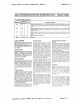
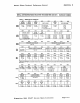
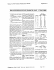
Table 2
REGISTER
BIT FORMATS (Contlnu.d)
BI17
BIT8
IIR
INPUT
DELTA
PORT
BREAK
B
CHANGE
O.no
O.no
1.
yes
1
ayes
BIT7
BIT6
IN. PORT
DELTA
CHANGE BREAK B
IMR
INT INT
0
..
011
0=
off
1
con
1=
on
CTUR
CTLR
cumulation
(logical
OR)
of
the status for
a"
characters coming to the top
of
the
FIFO since the last 'reset error' command
tor
channel A was issued.
MR1A[4:3) - Channel A Parity
Mod.
Select
-
If
'with
parity' or 'force parity'
is
lelected.
a parity
bit
is added
to
the trans·
mitted
character and the receiver per·
forms a
parity
check on incoming data.
MR1A[4:3] =
11
selects channel A
to
ope
r
•
.te
In the spbcial multidrop mode de·
scribed
in the Operation seCllon.
MR1A(2)
- Channel A Parity Type Select
- This bit selects
thE:
parity t)'pe (cdd
or
even)
If
the
'with
parity' mcde is program·
med by MR1A[4:3], and the polarity of the
forced parity
bIt if the 'force partty' mode
1&
programmed. It has no effect if the
'no
parity'
m"de
is programmed. In the special
multidrop
mode it selects the polarity
of
the
AID
bIt.
MR1AI1:0)-
Channel A
Bltl
per Character
Select - This field selects the
nU'11ber
'of
data
bits
per character to be transmItted
and received. The character
le
...
gt~
doe5
not
inc Iud!: the start. parity. and stop 0lt5
BITS
BIT4
BIT3
RxROYI
COUNTER
FFULLB
TxRDYB
READY
OD
no
011:
no
0=
no
1 = yes
1
ayos
1
eyes
BIT5
BIT4
BIT3
R_ROYI
T_ROYB
COUNTER
FFULLB
READY
INT
INT
INT
0=
off
0=
off
0=
off
1 = on
1 = on
1 = on
MR2A - Channel A Mode
Register 2
MR2A is accessed when the channel A MR
pOinter
points
to
MR2,
which occurs after
any access to MR1A. Accesses
to
MR2A
do not change the pointer.
MR2A[7:6) -
Channel A Mode Select -
Each channe!
01
the DUART can operate
Ir-
one
of
four modes. MR2A(7:61= 00 is the
normal mode.
with
the transmitter and
reo
ceiver operating independently. MR2A[7:6]
=
01
places the channel in the automatic
cchc
moos. which 3utorr.atica!!,
rctr~r.s
mits
the received data.
ThE:
following
c.on·
dillons
arc true while
In
automatic. ecnc.
mode:
1.
Received
dat~
IS
reclocked and retrans·
mltted
or.
the TxDA output.
2.
The receive clock is useo
lor
the
traM'
mitter.
3.
The receiver must
be
enabled, but the
transmitter need not
be
enableCl
4.
The charonei A TxRDY and TxEMT
status
bits
are inactive
5.
The received parity
IS
checked, but
IS
not regenerated for transmission.
I.e.
transmitted parity bit
IE
as
received.
BIT2
BIT1
alTO
DELTA
RxROYI
BREAK
A
FFULLA
TaROYA
O=no
0=
no
O.no
1 = yes
1 = yes
lzyes
~IT2
BIT1
alTO
DELTA
R.ROYI
TxRDYA
BREAK A
FFULLA
INT INT
INT
0=
off
0=
off
o.
off
1 = on
1 = on
1-on
6.
Character framing is checked, but the
stop bits are retransmitted
as received.
7 A received break is
eChoed as received
until
the next valid start
bit
is detected
8.
CPU
to
receiver communication contln·
ues normally, but the
CPU
to
transmit·
ter
link
is disabled.
Two
diagnostic modes can also be
conflg·
ured. MR2A!7:6J=
10
selects local loop·
bacK mode In thiS mode:
1. The transrTlltter output IS internally
connecteo
to the receiver .nPI.tt.
2 The transmll cloc
....
is
used for
tne
reo
ce!ver.
3.
Tr>e
·hDJ,. output
is
held
hlgt
•.
4. The
RJl.DA
Input
IS
Iwnored.
5.
The transmitter must be enabled. but
the rece:ve' need not be
en.:lled.
6.
CP:J
to transmitter and rece'ver com·
municatlons
continue
normal',.
The second diagnostIc mooe
IS
t
...
e remc!!:
loopba::~
mode. selected by MR2A!7:6j=
11.
In thiS mod(:
1 Recelvea data is relocked
anO
retran!.·
mIlled
0'"
the T"OA output
2.
;t'le receive
CIO::
...
IS
used for tt'le tra
...
!.
miller
Sign.tics
2681
DUART
Device
Specifications
Page
H-8