
Specifications


Multi
Slave
Product
Reference
Manual
Append1)i;; H
JANUARY 1983
DUAL
ASYNCHRONOUS
RECEIVER/TRANSMITTER
(DUART)
SCN2681
SERIES
receiver, by
connecting
the RTSN
output
to
the
CTSN
Input
of
the
transmitting
device.
If
the
receiver
is
disabled, the FIFO char·
acters can be read. However, no additional
characters can be received
until
the
reo
ceiver
is
enabled again. If the receiver is
reset, the
FIFO and all
of
the receiver
status, and the corresponding
output
ports
and
interrupt
are reset.
No
addi·
tional characters can be received
until
the
receiver
is
enabled again.
Multidrop
Mode
The DUART is equipped
with
a wake up
mode
used
for
multidrop
applications.
This
mode
is
selected by programming
bits
MR1AI4:3) or MR1B[4:3)
to
'II'
for
channels A and B respectively.
In thiS
mode
of
operation, a
'master'
station
transmits
a"
address character followed
by
data
characters
for
the addressed
'slave' station. The slave stations,
witt"'
receivers
that
are
normally
disabled, ex·
amine
the received data stream and 'wake·
up'
the
CPU (by
setting
RxRDY) only upon
receipt
of
an address character. The CPU
compares the received address
to
its
sta·
tion
address and enables the receiver
if
it
wishes
to
receive the subsequent data
characters. Upon receipt
of
another ad·
dress character,
the
CPU may disable the
receiver
to
initiate
the
process again.
A
transmitted
character
consists
of
a
sta~t
•
bit,
the programmed number c
f
data bits.
an address/data (A/D) bit, and the pro·
grammed
r,umber
of
stop
bits. The
polarity
of
the
transmitted
AID bit is selected by
the
CPU by programming bit MRIA[2)'
MRIB[2).
MRIA[2)/MRIB[2)=
0
transmits
a
zero in the AID
bit
position.
which
Iden·
tifies
the
corresponding
data
bits
as
data.
while
MRIA[2)/MRIB[2J= I
transmits
a
one in the AID bit
position.
which
identl.
fies the
corresponding
data
bits
as an ao·
oress. The
CPU
should program the modf.
register
prior
to loading the corresp':lndinG
data
bits
into
the THR.
In
this
mode, the receiver
continuously
loOkS
at the received data stream. whet
he'
it
IS
enabled or disabled. If disabled. it
sets
the RxRDY
status
bit and loads
thE:
character
into
the RHR FIFO if the
reo
ceived AID bit is a one (address tag,. but
aiscaras the receivea character
If the
received
AID
bit is a zero (data
te.g).
If
enabled, all received characters are trans·
ferred to the
CPU
via the RHR. In either
case. the data
bits
are loaded
Into
the data
FIFO
while
the AID bit
IS
loaded
Into
thE:
status FIFO
position
normally used for
pa~lty
error
(SRA[5J
or
SRB:5)1
FraminG
error. overru,", error. and breat
d~te~t
oper·
ate normally whether
or
not the receiver is
enabled.
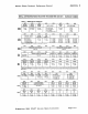
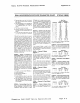
PROGRAMMING
The operation
of
the DUART is program·
med by
writing
control
words
into
the ap·
propriate registers. Operational feedback
is provided via status registers which can
be read by the
CPU. The addreSSing
of
the
registers is described in
table
I.
The
contents
of
certain
control
registers
are
inlt
lalized
to
zero on RESET. Care
Should
be
exercised if the
contents
of a
register are changed during operation,
since certain changes may cause
opera·
tional
problems. For example, changing
the
number
of
bits
per character while the
transmitter
is active may cause the trans·
mission
of
an
Incorrect character.
In
gen·
eral,
the
contents
of the MR, the CSR, and
the OPCR should only
be
changed while
the receiver(s) and transmitter(s) are not
enabled. and certain changes to the
ACR
should only
be
made while the CfT is
stopped.
Mode registers
I and 2
of
each channel are
accessed via independent
auxiliary point·
ers. The
pointer
is set to
MRlx
by
RESET
or by
issuing
a 'reset pointer' command
via the corresponding command register.
Any read
or
write
of
the mode register
while
the pOinter is at
MRlx
switches the
pOinter to MR2x. The
painter
then remains
at
MR2)<.,
so that subsequent accesses are
always
to
MR2x unless the pOinter is reset
to
MRlx
as
described above.
Mode, command, clock select.
anj
status
regl~ters
are
duplicated
for each channel
to provide
total
independent operation
and
control.
Refer to table 2
fcr
register bit
des':flptions.
MR1A - Channel A Mode
Register 1
MRIA
IS
accessed when the chann('1 A MR
pointer
points
to
MRI.
The
pointer
is
set
to
MR1
by RESET or by a
'set
r)ointer' com-
mand applied via CRA.
After
reading
or
wntlng
MRIA,
the
pointer
will
point
to
MR2A.
MR1A(7] - Channel A Receiver Request·
to-Send
Control
- This bit
controls
the
deactivation
of
the RTSAN
output
(0
PO)
by
the receiver. This
output
is
normally
asserted by
setting
OPR[O)
and negated by
resetting
OPR(O).
MRIA(7)=
I
causes
RTSAN
to
be negated upon receipt
of
a
valid start
bit
if the channel A FIFO
is
full.
However.
OPR[O)
is not reset and RTSAN
will
be
asserted again when an
empty
FIFO pOSition is available. This feature
can be used for
flow
control
to
prevent
overrun in the receiver by
using
the
RTSAN
output
signal to
control
the CTSN
input
of
the
transmitting
deVice.
MR1A[6] - Channel A Receiver
Interrupt
Select - ThiS
bit
selects
either
the chan·
nel
A receiver ready
status
(RXRDY)
or
the
channel A
FIFO full
status
(FFULL)
to
be
used
for
CPU interrupts.
It
also
causes
the
selected
bit
to
be
output
On
OP4
if it
is
programmed as an
interrupt
output
via the
OPCR.
MR1A[5] - Channel A Error Mode Select
- ThiS bit selects the operating
mode
of
the three FIFOed
status
bits
(FE,
.PE,
reo
ceived break) for channei
A.
In the 'chara::-
ler'
mode, status is provided on a charac-
ter·by·character basis: the
status
applies
onl,' to the character at the top
of
the
FIFO.
In
the 'bIQcl\' mode, the status pro-
Vided
In
the
SR
for these
bits
is the ac-
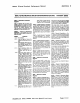
Table 1
2681
REGISTER ADDRESSING
I
~
I
~
! 0
o
! 0
I
~
I'
I I
I
~
I
~
READ
(RON
=
0)
WRIlE (WRN =
01
Mode
Regi~ter
A (MR1A. MR2A) Mode Register A (MR1A. MR2A)
Status
Register A (SRA) Clock Select Reg. A (CSRA)
"Reserved"
Commesnd
Register A
(CRA:,
RX
Holding Register A (RHRA) I
TX
HalOing
Registe'
A (THRA)
Input Port Change
Reg
(IPCR) I Aux. CO"ltrol Register (ACR,
Interrupt Status
Reg.
(ISRI Interrupt Masi': Reg.
(\~AR,
CounteriTimer Upper
(CTU)
CfT
Upper Registe'
(CiUR
CounterfTlmer Lower \CTL) I crr Lower Register (CTLR)
Mode Register B.(MRIB, MR2B} I Mode Register B (MR1B
~R2Bi
Status Register 8 (SRB) Clock Select Reg. B (CSR5;
"Reserved"
Command Register B ICRe!
RX
Holding Register B (RHRB)
TX
HOldl'lg Register B ITHRB)
"Reserved"
I "Reserve::l"
Input Port I
Output
Port Conf
Reg
(OpeRI
Start Counter
Comma-,j
I Set
Output
Port Bits COT-rnane
Stop
C(jurtt~r
Command Re'set Output Port 81ts Comrnanc .
5ignetics
2681
DUART
Device
Speci£ications
Page
H-6