
Specifications


Multi
Slave
Product
Re£erence
Manual
Appendix
H
DUAL
ASYNCHRONOUS
RECEIVER/TRANSMITTER
(DUART)
SCN2681
SERIES
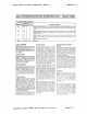
Output Port
The 8·bit
multl·purpose
output
port
can be
used as a
general purpose outPut port,
In
which
case the
outputs
are the comple·
l')'1ents
of
tne
output
port register (OPRI.
OPR!n)
= 1 results
In
OP!n):: low and vice·
versa.
Bits
at
the OPR can be individually
set and
r<;!sel.
A
bit
IS
set by oerformlng a
'Nrite operat:on at address
E'6
with
the ac·
companying
J.lIa
specifYing
t~e
bits to be
set
(1
::
set, 0 = no change). Likewise, a bit
is
reset by a
write
at address F'6
with
the
accompanying
data
specifYing the
bits
to
be reset
(1
= reset,
0=
no change).
Outputs
can be also individ..,ally assigned
specific
functions
by
appropriate
pro·
grammlng
of
the
channel A mode registp.rs
iMA1A.
MR2A), the channel 9 mace regis·
ters
IMAI8.
MA28), and the
output
port
conf:gl.ration
register
IOPCR)
OPERATION
Transmitter
The
2681
is
conditioned
to
transmit data
when the
transmitter
is enabled through
the
command
register. The
2681
indicates
to
the
CPU that
it
is
ready
10
accept a
character
by
setting
tM
TxRDY
bit
in the
status
register. This
condition
can be pro·
grammed
to
generate an
interrupt
request
at
OPS
or OP7 and INTAN. When a charac·
ter
is
loaded
Into
the
transmit
holding
reg·
Ister
(THA), the above
conditions
are
negated. Data
is
transferred from the h
~,Id·
ing
register
to
the
transmit
')hift register
.....
hen
it
is
Idle
or
has completed transmis·
sion
of
the previous character. The TxADY
conditions
are then asserted again whiCh
means one
full
character
time
of
outterlng
IS
provided. Characters cannot be loaded
Into
~he
THA
while
the
transmitter
is diS'
abled.
The
transmitter
converts
the parallel data
from
the
CPU
to
a serial
bit
stream on the
TxD
output
Pin. It
automatically
sends a
start
bit
followed
by the programmed
number
of
data
bits, an
optional
parity bit,
and
the
programmed
number
of
stop bits.
The
least Significant
bit
is sent first. Fol-
lowing
the
transmission
of
the stop bits,
if
a new
character
is
not available in the
THA,
the
TxD
output
remains high and
th~
TxEMT
bit
in
the
status
register
(SR)
will
be set
to
1.
Tran5mission resumes and the
TxEMT
bit
is
cleared when the CPU loads a
new
character
into
the THR.
If
the trans-
mitter
is
disabled,
it
continues
operating
until
the
character
currently
being trans-
mitted
is
completely
sent
cut.
The trans-
mitter
can be forced
to
send a continLOous
lOW
condition
by ISSUing a send break
command.
The
transmitter
can be reset through a
software command.
If it
is
reset, operation
ceases immediately and the
transmitter
must
be
enabled
through
the command
register before resuming operation.
If eTS
operation
IS
enabled, the CTSN
input
must
be low in order for the character to be
transmitted.
If It goes high in the middle
of
a transmission, the character in the
shift
register is
transmitted
and TxDA then
re-
mains
In
the marking state
until
CTSN
I)Oe5
low. The
transmitter
can also control
I~e
~jeactl'l<ition
of
Ire
ATSN output.
If
programmp.d, the RTSN
output
will
be
re-
set
on~
bit tlrne
atter
the character in the
transmit
shift
register and
transmit
hold-
ing register (if any) are
completely
trans-
mitted,
if
the
transmitter
has been dis-
abled.
Receiver
The
2681
is
conditioned
to receive data
when enabled through the command (eg'
Ister. The receiver looks
for
a high
to
low
(mark to space)
transition
of
the
start bit
on the RxD
input
pin. If a
transition
is
de-
tected, the state
of
the AxD pin is sampled
dach t6X cloCk for
7·112
clocks
(16X clock
mode)
or
at the next riSing edge
of
the
bit
time
clock
(1X
clock
mode). If
RxD
is
sampled high, the start
bit
is invalid and
tM
search for a valid start
bit
begins
:lgain.
It
AxD is
still
low, a valid start
tit
is
assumed and the receiver continues to
sample the input at one
bit
time intervals
at
tre
theoretical center
of
the bit, until
the proper
number
of
data
bits
and the
panty
bit (if any) have been assembled,
and one stop
bit
has been detected. The
least
sigificant
bit
IS
received first.
rhe
data
IS
then transterred
to
the receive
holding
register (AHA) and the AxRDY
bit
in the
SA
is set
to
a
1.
This
condition
can
be programmed
to
generate
an
interrupt at
OP4 or
OPS
and INTMN. If the character
len~th
IS
less than
eight
bits, the
most
Significant unused
bits
in the AHA are set
to zero.
After
the
stop
bit is detected, the receiver
Will Immediately look for the next start bit.
However,
If a non-zero character was
re-
ceived Without a stop
bit
(framing error)
and RxD remains
low
for
one half
of
the bit
period after the stop
bit
was sampled,
tnen the receiver operates as
if
a new start
bit
transition
had been detected at that
point
(one-half bit
time
after the stop
bit
was sampled).
The parity error,
framing error, overrun er·
ror and received break state lit any) are
S!gnetics
2681
DUART
Device
Specifications
strobed
Into
the
SA
at the received charac·
ter boundary, before the AxRDY status
bit
is set. If a break
condition
IS
detected
(AxD
IS
,ow for the
entire
character in-
cluding
the stop bit), a character con·
sisting
of
all zeros
will
be loaded
Into
the
AHR and the received break bit in the SA
is set to
1.
The AxD
input
must return to a
h:gh
condition
for at least one·half
bit
time
before a search for the next start
bit
beginS.
The AHA
consists
of
a first·in·first-out
(FIFO)
stack with a capacity
of
three char-
acters. Data is
Ie"aded
tram the receive
shift
register Into the
topmost
empty posi-
tion
I)f the FIFO. The AxADY
bit
In
the
status
register is set whenever one
or
more
characters are available to be read,
and a FFULL status
bit
is set
if
all three
stack
pOSitions are filled With data. Either
of
these
bits
can be selected
to
cause an
interrupt.
A read
of
the AHR
outputs
the
data at the top
of
the FIFO.
After
the read
cycle, the data FIFO and
its
aSSOCiated
status
bits
(see below) are 'popped'
thus
emptying
a FIFO
position
for
new data.
In
addition
to the
data
word, three
status
bits
(panty error, framing error, and
re-
ceived break) are also appended to each
data character
In
the FIFO (overrun
is
not).
Status
can
be
provided in
two
ways, as
programmed by the error mode
control
bit
in the
mode
register. In the 'character'
mode,
status
is orovided on a character-
by·character
basis: the
status
applies
only
to the ct1aracter at the top
of
the FIFO. In
the
'block'
mode, the
status
provided in
the
SR
for
these three
bits
is
the logical
OA
of
the
status
for
all characters
coming
to the top
of
the FIFO since the last 'reset
error'
command was Issued. In
either
mode
reading the SA does not
af'ect
~he
FIFO. The FIFO
is
'popped' only when the
AHR is read. Therefore tne status register
snould be read prior
to
reading the FIFO.
If the FIFO is full when a new character
is
received, that character is held
in
the
re-
ceive
shift
register
until
a FIFO
position
is
available.
If
an
additional
character
is
re-
ceived while
this
state
exits, the
contents
of
the FIFO are not affected: the character
previously in the
shift
register is
lost
and
the overrun error status
bit
(SA[4)) Will be
set upon receipt
of
the
start
bit
of
the new
(overruning) character.
The receiver can
control
the deactivation
of
ATS.
If
programmed
to
operate
in
this
mode, the ATSN
output
will
be negated
when a
valid start
bit
was received and
the
FIFO
is
full. When a FIFO
position
be-
comes available, the RTSN
output
Will be
re-asserted automatically. This feature
can be used
to
prevent an overrun, In the
Page
H-5