
Specifications


Hulti
Slave
Product
Re£erence
Manual
Section
3
FAULT ISOLATION
Fault
isolation
is
the
process
o£
identifying
a
fault
and
the
resultant
cause
of
the
£ault
to
the
lowest
possible
level.
This
section
deals
with
hardware
fault
isolation
and
is
generally
independent
o£
so£tware
considerations.
Prior
to
any
attempt
at
fault
isolation,
a
test
environment
must
be
validated.
Generally,
the
test
environment.
will
consist
o£
an
5-100
chassis,
motherboard,
power
supply,
S-100
extender
card,
snd
a
known
good
Multi
Slave.
Validation
consists
o£
removing
all
other
5-100
circuit
cards
from
the
chaSSiS,
and
any
other
devices
loading
the
+8,
+16,
and/or
-16
VDC
power
supplies.
Having
removed
all
circuit
boards
from
the
motherboard,
verify
that
the
£ollowing
voltages
referenced
to
ground
(5-100
bus
pin
50
and
100)
are
within
the
tolerances
listed
below:
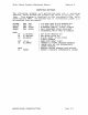
S-100
PIN
DEFINITION
MINIMUM AVERAGE
MAXIMUM
---------
----------
-------
-------
-------
1
+
8
VDC
+7.0
+11
.0
+25.0
51
+
8
VDC
...
7.0
"'11.0
...
25.0
2
+16
VDC
+14.5
+21.5
+35.0
52
-16
VDC
-35.0
-21.5
-14.5
The
above
conditions
must
be
met
before
proceeding
with
the
next
teat..
Step
1:
Visual
V~rificdtion
Inspect
the
suspect
Multi
Slave
to
verify
that
components
correctly
installed
and
properly
seated
in
their
sockets.
ponents
may
be
compared
against
a
known
good
Multi
Slave.
DIP
components
have
t.he
Bame
pin
1
orient.ation.
Step
2:
On
Board
+5
VDC
Regulation
are
Com-
All
Remove
power
from
the
motherboard.
Insert
the
S-100
extender
card
into
a
suitable
slat
in
the
motherboard,
then
insert
the
Multi
Slave
into
the
extender
card
Bocket.
Apply
power
and
measure
the
voltage
at
Ul-16.
This
voltage
must
be
between
4.75
and
5.25
VDC.
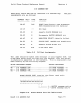
Step
3:
Clock
Veri£jcat~an
Veri£y
the
clock
£requenciea
at
the
£ollow1ng
locations:
U57-7
80ns
U49-8
150ns
FAULT ISOLATION
central
clock
distr~buted
to
all
CPU"s.
central
SIO
clock
distr~buted
to
all
DUART's.
Page
3-1