
Specifications


Multi
Sleve
Product
Reference
Manual
Section
1
.....
...
A
....
..
~
rt
..
+-
.--+
2681
-fJ
DUARl
f4-
..
po'
....
..
----.
...
r--
~
...
~
..
...
PROM
.1
Z80-H
CPU
~
..
..
...
Bank
...
(1
of
3)
>---
r-----.
Control
64k
& Timing
RAM
'--
r-
~
L_---..
p,
..
I
NTER-
S-100
FACE
....
BUS
"-
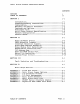
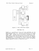
Figura
1-1
Mult!
Slave
Block
D1agraa
FUNCTIONAL
FLOW
Figure
1-1
illustrates
the
maJor
£unctionsl
components
of
the
Multi
Slave
computer
board.
Initially.
immediately
following
the
power-on/reset
event,
all
three
processors
are
held
in
a
reset
state.
Each
processor
must
be
individually
activated
by
e
net-
work
master.
Once
t.he
master
has
activated
a
Multi
Slave
pro-
cessor~
the
selected
slave
CPU
then
begins
executing
the
instruc-
tions
provided
by
the
onboard
EPROM.
Depending
upon
user
response
and
intervention,
the
proceenor
will
either
initiate
the
execu-
tion
of
the
resident
Monitor/Debug
program,
or
begin
the
download
request
sequence
to
receive
an
operating
system.
MAJOR
FUNCTIONAL
FLOW
Page
1-4