
User`s guide

Chapter 4. Expansion Pedestal Option
EK–SMCPO–UG. A01 4–5
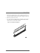
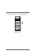
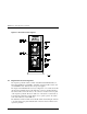
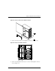
The EMU (Figure 4–4) is an internal circuit board, which monitors the operation
of the pedestal. The EMU monitors power supply voltages, fans, temperatures
that are reported to the user, and controls (turns on and off) the audible alarm and
status LED on the front panel of the pedestal. It is connected to the SCSI bus and
powered by internal cabling. The following external components on the rear
panel of the expansion pedestal are part of the EMU board:
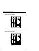
•
The alarm switch (S1) that enables (up) or disables (down) the audible alarm
•
The External Fault Condition connector allows the EMU to monitor the status
of a user-selected device
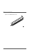
Figure 4–4 EMU Circuit Board Location
3
0
0
0
-
3
7
EMU
4.4 Reconfiguring Base Pedestal UltraSCSI Bus
WARNING
Only qualified service personnel should reconfig-
ure the base pedestal
. Dangerous voltages are
present within the subsystem. To prevent electrical
shock, always turn the subsystem off and discon-
nect the power cords before removing the side
panel.