
User`s guide

Chapter 3. Maintenance
EK–SMCPO–UG. A01 3–19
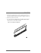
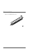
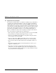
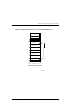
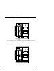
5. Installed the two replacement memory modules by aligning the module and con-
nector pins (check alignment guide in center of module) and gently pivot the mod-
ule the main controller board until it snaps into place (see Figures 3–14 and 3–15).
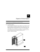
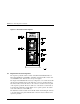
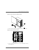
6. Replace the controller into the pedestal.
7. Power on the UPS and pedestal and check the activity LEDs on the front panel of
the controller. The reset switch/LED should begin to flash at a half-second rate
(heartbeat) and the host activity LEDs should flash.
Figure 3–14 Install Replacement Modules