
User`s guide

Chapter 3. Maintenance
EK–SMCPO–UG. A01 3–13
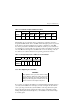
Table 3–2 SCSI Bus Length and External Cables
Bus Rate Bus Length Longest DIGITAL Cable
Speed MT/s MB/s Meters Feet Number Meters Feet
Fast 20 40 25 82 BN21K-23
BN21L-23
23 82
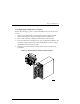
The SCSI bus in your pedestal is factory-configured as a split bus. One bus is
designated bus
D0
and the other as bus
D1
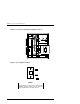
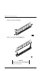
. An internal eight-position step switch
in the cabinet controls the SCSI bus device address configuration of the SBB
slots in the pedestal. For the RAID Array 3000, the switch is preset at the factory
to configuration “6”. This results in a device slot address assignment of 8 through
11 for bus
D0
and 8 through 10 for bus
D1
. Table 3–3 shows a listing of the de-
vice addresses for each bus and their corresponding pedestal slot location.
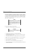
Table 3–3 Assigned Slot Device Addresses in the Pedestal
Slot #
0 12 3 456
Bus D0 D1
Device
Address
8 9 10 11 8 9 10
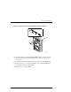
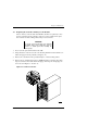
3.7.1 Reconfiguring the SCSI Bus
WARNING
Only qualified service personnel should reconfig-
ure the SCSI bus
. Dangerous voltages are present
within the subsystem. To prevent electrical shock,
always turn the subsystem off and disconnect the
power cords before removing the side panel.
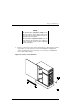
If you want to reconfigure the SCSI bus (to add the Expansion Pedestal Option to
your subsystem installation for example) you must reconfigure the bus. This in-
volves powering down the subsystem installation, removing the left side panel,
and reconfiguring the bus by changing the setting of the configuration switch.
Adding the Expansion Pedestal Option to your installation is described in Chap-
ter 4 of this guide.