
User`s guide

Chapter 3. Maintenance
EK–SMCPO–UG. A01 3–11
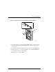
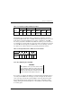
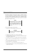
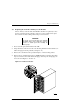
Figure 3–7 Remove Nuts from UPS and External Fault Connectors
3000-49
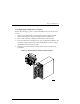
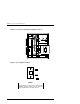
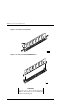
10. Align the connectors on the replacement EMU with the connector holes on
the rear panel and replace the mounting studs to secure the board (
do not
over-tighten
).
11. Reconnect the two ribbon cables to the rear connectors on the EMU board.
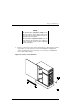
12. Replace the side cover on the pedestal and secure it with the TORX-head
screw on the front bezel of the pedestal.
13. Replace the door on the pedestal.