
User`s guide
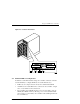

RAID Array 3000 Pedestal Enclosure
2–6 EK–SMCPO–UG. A01
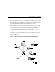
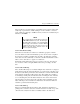
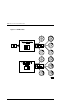
2.3 Controller Reset and LED Indicators
Figure 2–3 illustrates the front panel of the controller. All LEDs are numbered
from left to right. The reset button (LED 0) flashes green about once every sec-
ond (heartbeat) to indicate that the controller is operating normally. LEDs 1
through 4-display host and disk channel activity (amber). LED 5 (normally off)
comes on red during a controller failure. The LED/Reset switch interface is de-
fined in Table 2–2.
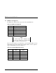
Table 2–2 LED/Reset Switch Interface
LED # Name
0 Heart Beat Controller Reset Switch (green)
1 Host Channel 0 Activity LED (amber)
2 Host Channel 1 Activity LED (amber)
3 Disk Channel 0 Activity LED (amber)
4 Disk Channel 1 Activity LED (amber)
5 Fault LED (red)