
User`s guide


RAID Array 3000 Storage Subsystem
1–10 EK–SMCPO–UG. A01
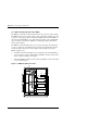
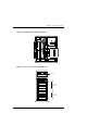
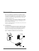
Figure 1–6 UltraSCSI Bus Port and Default SCSI ID Assignments
ID9
ID9
ID 11
ID8
ID8
ID10
ID10
Top Controller
Device
Port 0
Device
Port 1
Bottom Controller (Optional)
ID=7
ID=6
ID=7
ID=6
3000-51
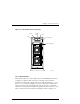
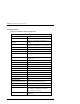
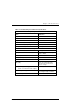
When set to a specific position, the switch controls the addresses of each SBB
slot. Figure 1–8 identifies the pedestal slot locations and their corresponding
SCSI ID addresses for each device port.
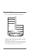
The subsystem can be reconfigured for “through-bus” operation by modifying the
bus and resetting the internal configuration switch. The information needed to
reconfigure the bus from “split-bus” to a “through-bus” configuration is de-
scribed in Chapter 4 of this guide (
Expansion Pedestal Option
).