
Installation guide


Chapter 1. Expansion Pedestal Option
EK–SM3KA–IG. A01 1–9
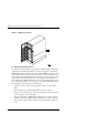
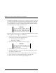
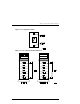
11. Remove the “knock-out” plate located above the D1 OUT label on the rear
panel of the base pedestal (see Figure 1-9).
Figure 1–9 Remove Connector Knockout Plate
3000-45
Remove Knockout
from D1 Out
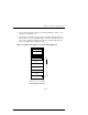
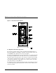
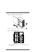
12. Connect cable assembly 17-04454-01 between the D1 OUT bulkhead open-
ing and the device # 1 backplane connector (see Figure 1-10). Secure the
bulkhead connector by tightening the two 6-32 SEM screws.