
Installation guide

RAID Array 3000 Storage Subsystem
6 EK–SM3KC–IG. C01
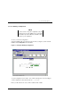
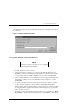
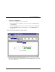
CTRL/C to abort the load sequence. A "
FLASH Boot Utility Options
" menu
should be displayed.
6. Choose menu item (2), Change serial baud rate. Select 38400. When presented
with the "Please change your baud rate and press RETURN" message, do so from
within HyperTerminal via the
File\Properties
menu, then choose ‘
Configure.
..
If there is no response from the utility after changing the baud rate, proceed with
Step 6.
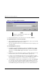
7. After changing the baud rate, you may have to close and re-enter HyperTerminal.
Press the RETURN key after HyperTerminal restarts. You should see
the
FLASH Boot Utility Option
menu again.
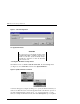
8. Select menu item “
1) Download new Firmware Image
”. Using the Transfer
menu in HyperTerminal, choose
Send Text File
and send the firmware. You
should see a "
Receiving code for System Version <ver>"
message, followed by
a series of \ | / - characters cycling at the end of the line. At 9600 baud, the
download will take between 45-60 minutes. At 38400, it should take around 10-
12 minutes. At completion, you'll see the
FLASH Programming complete
mes-
sage, followed by the
FLASH Boot Utility Options
menu again.
9. Select item 9,
Restart Controller
. You'll be instructed to reset the baud rate
back to 9600, which you'll again do from the HyperTerminal
File \Properties
\Configure
... menu. As before, you'll probably have to exit and restart Hy-
perTerminal to get any response. Press Enter when Hyperterminal restarts.
10. Your firmware should now be upgraded.
2.3 Shut down RA3000
1. Ensure that both host ports are in a quiescent state (no I/O activity).
2. Shut down the Host System.
3. Issue a “shutdown” command from the SWCC Console to the pedestal (or con-
troller shelf) controller.
4. Power
OFF
the pedestal or controller shelf as applicable.
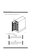
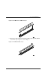
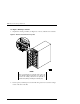
2.4 Install Two SIMMs in second controller
1. Install two of the SIMM modules into the second controller (make sure all SIMM
modules are of the same type) by aligning the connector pins and inserting the
modules into the SIMM module connectors as shown in Figure 6.