
Technical data
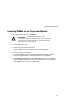


Installing Disk and Tape Drives
7-5
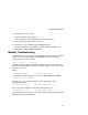
Storage Backplane
Your storage backplane supports seven hot-swap drives split between two SCSI bus
sections: SCSI Channel 1 and SCSI Channel 2 (see Figure 7-1). SCSI Channel 1 is
the upper bus section and consists of four SCSI device connections. SCSI Channel
2 is the lower bus section and consists of three SCSI device connections. These
channels can be configured as two independent SCSI buses or as one SCSI bus
(factory default) by installing a wide SCSI jumper cable.
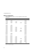
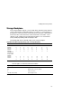
The following table lists the SCSI ID settings for the storage backplane.
Single/Dual SCSI Bus Target ID Settings (J181 on Storage Backplane)
Jumpers Set None W1
(1)
W2 W3 W1+W2 W1+W3 W2+W3 W1+W2+W3
SCSI Bus 1
Slot0 ID=
Slot1 ID=
Slot2 ID=
Slot3 ID=
0
1
2
3
0
1
2
3
8
9
10
11
0
1
2
3
8
9
10
11
0
1
2
3
8
9
10
11
8
9
10
11
SCSI Bus 2 or
Jumper Cable
Slot4 ID=
Slot5 ID=
Slot6 ID=
0
1
2
4
5
6
0
1
2
8
9
10
4
5
6
12
13
14
8
9
10
12
13
14
(1)
Factory default settings
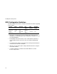
Refer to Figure 7-1 for the listed connector locations.
Figure Legend Description
A Wide SCSI connectors (68-pin)
B
(1)
Narrow SCSI connectors (50-pin)
C Power connectors
J181 (W1, W2, and W3) SCSI ID jumper block
(1)
Not supported