
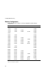
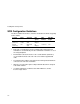
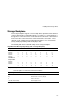
Technical data
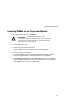


Installing Disk and Tape Drives
7-3
Tape Drive Configuration Guidelines
•
Tape drives should be installed in the upper 5¼-inch drive bays.
•
A full-height tape drive occupies two half-height 5¼-inch drive bays.
•
Use the secondary IDE controller to connect an IDE tape drive and observe
the following guidelines.
1. Attach the supplied IDE cable and configure the drive for ”master”
operation.
2. Change the “Local bus IDE adapter” field in the BIOS Setup Utility to
BOTH to enable the secondary connector.
•
Use a SCSI controller card to connect to a SCSI tape drive.
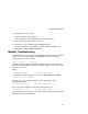
Hot Swap Drive Configuration Guidelines
•
A maximum of seven hot swap drives can be installed and configured in the
server.
•
Hot swap drives must only be installed in the hot swap drive bay.
•
A SCSI ID for each hot swap drive is assigned by the jumper settings on the
storage backplane.
Refer to the Single/Dual SCSI Bus Target ID Settings table in the Storage
Backplane section.
•
The storage backplane is factory-defaulted as a single channel on a wide
Ultra SCSI bus. Split the backplane by removing the jumper cable between
hot swap drives four and five. Properly terminate both sides of the
backplane, and then connect the spare SCSI cable from channel 2 on the
main logic board to the storage backplane.