
User`s guide

3.9 Serial ROM
3.9 Serial ROM
The serial ROM (SROM) provides the following functions:
• Initializes the CPU’s internal processor registers (IPRs)
• Sets up the microprocessor’s internal L1/L2 caches
• Performs the minimum I/O subsystem initialization necessary to access the
realtime clock (RTC) and the system’s flash ROM
• Detects CPU speed by polling the periodic interrupt flag (PIF) in the RTC
• Sets up memory and backup cache (Bcache) parameters based on the speed
of the CPU
• Wakes up the DRAMs
• Initializes the Bcache
• Copies the contents of the entire system memory to itself to ensure good
memory data parity
• Scans the system flash ROM for a special header that specifies where and
how the system flash ROM firmware should be loaded
• Copies the contents of the system flash ROM to memory and begins code
execution
• Passes parameters up to the next level of firmware to provide a predictable
firmware interface
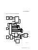
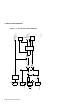
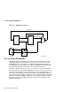
Figure 3–7 is a simplified diagram of the SROM and serial port logic.
Signal srom_oe_l selects the input to the multiplexer in the MACH210A
programmable logic device (PLD) (eb164.30). The multiplexer selects either the
output of the Xilinx XC17128 SROM (real_srom_d) or a user-supplied input
through the test SROM port (test_srom_d). The multiplexer output (srom_d)
provides data input (srom_dat) to the 21164.
After the initial SROM code has been read into the 21164’s Icache, the test
SROM port can be used as a software-controlled serial port. This serial port
can be used for diagnosing system problems when the only working devices
are the microprocessor, the SROM, and the circuits needed for the direct
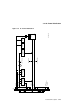
support of the microprocessor and SROM such as the clock. Connector J13 (see
Figure 2–3 and Table 2–2) supports an RS232 or RS422 terminal connection
to this port by using 1488 and 1489 line driver and receiver components.
Additional external logic is not required.
Functional Description 3–21