
User`s guide

B.9 Flash ROM Structure
B.9 Flash ROM Structure
During the power-up and initialization sequence, the EB164 always loads the
first image if BOOT_OPTION=1 (jumper J1—25/26 not installed). Then the
first image (the debug monitor) will be booted.
If jumper J1—25/26 (BOOT_OPTION) is installed (see Figure 2–2), the EB164
reads the value at location 0x3F of the TOY RAM. The EB164 uses the value
found there to determine which image will be selected (see Table B–6). The
selected image is loaded and executed.
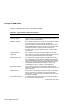
Table B–6 Flash ROM Image Selection
TOY RAM
Value
1
Firmware ID
2
Image Description
0x00 0 Evaluation board debug monitor firmware
0x01 1 Windows NT ARC firmware
0x02 2 Alpha SRM firmware (OpenVMS)
3
0x03 2 Alpha SRM firmware (Digital UNIX)
3
0x8n N/A
4
SROM code loads the nth image from flash ROM.
If n=0, the SROM code loads the entire flash ROM
contents.
If n=1, 2, . . . , the SROM code loads the first image,
second image, and so on.
1
Operating system type. Found at TOY RAM address 0x3F.
2
Found in image header.
3
Note: SRM firmware is not included in the EB164 kit.
The flash ROM contains only one of these images.
4
Not applicable.
If an image is specified and is not found, the EB164 loads the first image found
in the flash ROM with a valid header. If no valid header is found, the entire
1MB flash image is loaded at address 0x00000000.
The following sequence of steps describes how to change the value stored in
TOY RAM location 0x3F using either the basic debug monitor commands or
the debug monitor
bootopt
command.
B–12 SROM Initialization