
User`s guide

B.2 Firmware Interface
Table B–1 (Cont.) Output Parameter Descriptions
Output Parameter Parameter Description
r21 (a5)—System context
value
The context value is interpreted in a system-specific
manner. If the system needs to pass more than one
system-specific parameter, then it may pass a context
value. A context value is a physical address pointer to a
data structure of many system-specific values.
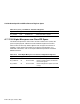
B.3 Automatic CPU Speed Detection
The EB164 real-time clock (RTC) detects the speed of the CPU. This allows a
somewhat generic SROM to support EB164 systems configured for different
CPU speeds. The speed is determined by counting CPU cycles between RTC
interrupts that are set to occur at known time intervals (1/8 second).
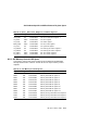
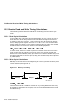
B.4 CPU Bus Interface Timing
The EB164 Bcache timing is based on CPU speed in addition to fixed delays
associated with the Bcache subsystem. The pertinent Bcache delays used in
the calculations result from the logic devices used in the Bcache subsystem,
SRAM specifications, and board etch delays. This data is used to calculate
the appropriate BIU_CTL register setting, which determines the CPU pin bus
timing.
Table B–2, Table B–3, and Table B–4 describe the fixed delays for the EB164.
Table B–2 Cache Loop Delay Characteristics
Function Description
Tadr Index line delay from CPU to SRAM pins
Tbuf Buffer gate delay
Tdat Data path delay between CPU and SRAM pins (and vice versa)
Toe1 Delay from CPU to the inverting buffer in the OE path
Toeb Inverting buffer delay
Toe2 Delay from the inverting buffer to the SRAM outputs
Twe1 Delay from CPU to the inverting buffer in the WE path
Tweb Inverting buffer delay
Twe2 Delay from the inverting buffer to the SRAM inputs
B–4 SROM Initialization