
User`s guide

B.2 Firmware Interface
Table B–1 (Cont.) Output Parameter Descriptions
Output Parameter Parameter Description
r18 (a2)—Cycle count in
picoseconds
This value is the number of picoseconds that elapse for
each increment of the processor cycle count (as read
by the RPCC instruction). This may be a multiple of
the actual internal cycle count of the microprocessor
as specified in the Alpha AXP Architecture Reference
Manual (a microprocessor will increment the processor
cycle count a multiple of the microprocessor clock, where
the multiple is a power of 2, including 2
0
= 1).
r19 (a3)—Signature and
system revision ID
This register includes a signature that specifies that
the transfer is following the standard protocol and
that the other values can be trusted. In addition, the
signature can identify which version of the protocol is
being followed. The system revision is a 16-bit field that
communicates system revisions that would be significant
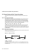
to operating system software. The register has the
following format:
Bits <63:32>
Bits <31:16>
Bits <15:0>
= Ignore
= Signature
= System Revision
Valid signatures have the following values:
0xdeca–V1 (previous version of this specification)
0xdecb–V2 (current version of this specification)
r20 (a4)—Active processor
mask
The processor mask identifies each processor that
is present on the current system. Each mask bit
corresponds to a processor number associated by the
bit number (for example, bit 0 corresponds to processor
0). A value of 1 in the mask indicates that the processor
is present, a value of 0 indicates that the processor is not
present.
To qualify as present a processor must be:
• Physically present
• Functioning normally
• Capable of sending and receiving interprocessor
interrupt requests
Uniprocessor systems pass a value of 1 to this register.
(continued on next page)
SROM Initialization B–3