
Specifications


1
OUTLINE
2
SYSTEM
CONFIGURATION
3
SPECIFICATIONS
4
GT CONVERTER2
SCREEN LAYOUT
5
GT CONVERTER2
OPERATION METHODSAPPENDICES
Appendix 2 Conversion Specifications for GP-PRO/PB III Series
Appendix 2.9 LS area
App - 36
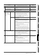
Word
address
Description Bit Remarks
GP → PLC Exclusive Reading Area
+8 Change Screen Number 1 to 8999 (However, 1 to 1999 when using BCD input)
<Example>
When the start address of the system data area is "D00000", the change screen
number is "D00008".
+9 Screen Display ON/OFF FFFFh: Screen clears almost immediately. 0h: Screen turns ON.
+10 Current YEAR
BCD 2 digits + flag
Last 2 digits
(Bit #15 is the clock's data write change flag.)
+11 Current MONTH, BCD 2 digits 01 to 12 (month)
+12 Current DAY, BCD 2 digits 01 to 31 (date)
+13 Current TIME, BCD 4 digits 00 to 23 hr, 00 to 59 min
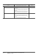
+14 Control
* Equivalent to the GOT system
information
Bits and corresponding bit status
* Make sure to turn off all reserved bits since they may be used for the GP system
maintenance and others.
+15 Reserved Set to 0.
+16 Window Control Bits and corresponding bit status
+17 Window Registration Number Global Window registration number selected by Indirect setup
(BIN or BCD)
+18 Window Display Position
(X coordinate data)
Global Window display coordinates selected by Indirect setup
(BIN or BCD)
+19 Window Display Position
(Y coordinate data)
Backlight OFF
Buzzer ON
Starts printing
Reserved
Buzzer
0: Enabled
1: Disabled
Bit 0
1
Reserved
2
4
5
9
AUX Output
0: Enabled
1: Disabled
PLC monopoly
0: Disabled
1: Enabled
VGA Display
0: Disabled
1: Enabled
Reserved
Hard copy output
0: Enabled
1: Disabled
Reserved
3
6
7
8
11
15
10
Window Display
0: Disabled
1: Enabled
Changing the order of
window overlapping
0: Possible
1: Not Possible
Reserved
Bit 0
1
15