
Specifications


App - 35
Appendix 2 Conversion Specifications for GP-PRO/PB III Series
Appendix 2.9 LS area
<Contents and range of system data area>
With the GP offline mode, specifying [STARTING ADDRESS OF SYSTEM DATA AREA] in [PLC SETUP] of
the INITIALIZE menu automatically prepares the system data area in the PLC.
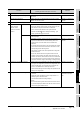
The following table shows the contents of the system data area.
Area
Word
address
Description Bit Remarks
GP → PLC Exclusive Writing Area
+0 Display Screen Number 1 to 8999 (However, 1 to 1999 when using BCD input)
+1 Error Status
Each bit changes according to the GP
error status.
When an error occurs, the
corresponding bit turns on.
Turning on, off, and then on the power
clears the bit.
0, 1 Not used
2 System ROM/RAM
3 Memory Checksum
4 SIO Framing
5 SIO Parity
6 SIO Over-run
7, 8 Not used
9 Memory requires Initialization.
10 Timer Clock Error
11 PLC
12 to 15 Not used
+2 Current YEAR
BCD 2 digits
Last 2 digits
+3 Current MONTH
BCD 2 digits
01 to 12 (month)
+4 Current DAY
BCD 2 digits
01 to 31 (date)
+5 Current TIME
BCD 4 digits
00 to 23 hr, 00 to 59 min
+6 Status Bits and corresponding bit status
* Monitor only the necessary bits in the bit unit.
Since reserved bits may be used for the GP system maintenance and others, their
ON/OFF status is not defined.
+7 Reserved -
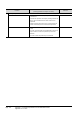
Bit 0
2
3
7
15
PLC monopoly
Now Printing
Writes a set value
Reserved
Reserved
K-tag entry error