
Specifications


1
OUTLINE
2
SYSTEM
CONFIGURATION
3
SPECIFICATIONS
4
GT CONVERTER2
SCREEN LAYOUT
5
GT CONVERTER2
OPERATION METHODSAPPENDICES
Appendix 2 Conversion Specifications for GP-PRO/PB III Series
Appendix 2.9 LS area
App - 34
Appendix 3.2 GP2000 system data
<System data area>
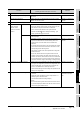
The GP2000 internal areas are collectively called LS area.
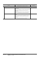
Twenty word addresses starting from the start address in the LS area are the system data area.
The system data area is a defined area that the GP occupies in the PLC memory to execute basic
operations, including the screen switching. In the area, a function is predetermined per address. The system
data area is a medium for the GP to exchange data with a host. By specifying an address of the PLC
memory in [PLC SETUP] of the INITIALIZE menu of the GP, the consecutive addresses starting from the
specified address are automatically assigned as the system data area in the PLC.
LS area
System data area
User area
*1
Special relays
*2
Reserved
*3
User area
*4
LS0
LS19
LS20
LS2031
LS2032
LS2047
LS2048
LS2095
LS2096
LS4095
System data area
Reading area
D100
D119
<Example>
Data memory, data register, and others
Start address of system data area
When the reading area is set in the
mode setting of the GP system
setting, addresses equivalent to the
specified number of points are
assigned as the reading area. The
reading area follows the system
data area.
The same assignment method is
applied to the LS area. The reading
area follows the system data area
(starting from LS20), and the
addresses equivalent to the specified
number of points are assigned as
the reading data.
*1 Area used for the functions that data is not required to be sent to the PLC, including the window display
*2 Area that functions like the GOT special registers. For details, refer to the PLC manual.
*3 Area used for function enhancement
*4 Area added with GP Ver4.0 or later
* Though the LS area retains data even though the GP is turned off, the GOT clears the data when the GOT
is turned off.
* With GT Converter2, the LS addresses are converted into the GOT data registers. Convert the converted
GOT data registers equivalent to the screen switching devices in a batch.
* For the microcomputer connection, the screen switching device set with GT Designer2 is not the PLC address
equivalent to the ninth address, starting from the start address of the system data area in the GP2000.
to
to
to
to
to