
Specifications


1
OUTLINE
2
SYSTEM
CONFIGURATION
3
SPECIFICATIONS
4
GT CONVERTER2
SCREEN LAYOUT
5
GT CONVERTER2
OPERATION METHODSAPPENDICES
Appendix 2 Conversion Specifications for GP-PRO/PB III Series
Appendix 2.9 LS area
App - 26
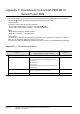
3 Conversion specifications of LS2032
The following indicates the conversion specifications of LS2032.
4 Conversion specifications of LS2033
The following indicates the conversion specifications of LS2033.
Bit
Conversion destination
device
Description Remarks
0 GS0.0 Alternates between ON and OFF every
communication cycle.
------
1 GS0.1 Turns ON during the time from screen
switching to tag processing completion.
------
2
------
Turns ON only when a communication
error occurs.
Converts into the status in which no device has
been set.
3 GS0.3 Turns ON while the initial screen is
displayed just after startup.
Normally kept ON.
------
4 GS0.4 Normally kept ON. ------
5 GS0.5 Normally kept OFF. ------
6
------
Turns ON when the backup SRAM data
is cleared.
Converts into the status in which no device has
been set.
7 GS14.7 Turns ON when D-Script is used then
BCD error occurred.
------
8 GS14.8 Turns ON when D-Script is used then 0
division error occurred.
------
9
------
Writes completion bit address (From
filing data to SRAM)
Converts into the status in which no device has
been set.
10 Transfer completion bit address
11 Keeps ON while filing data is being
transferred from SRAM to LS area by
the file item display.
12 GS14.12 Turns ON when D-Script is used then a
communication error is caused by
memcpy() or address offset call.
Turns OFF when data reading is
completed properly.
------
13 to 15
------
Reserved area Converts into the status in which no device has
been set.
Bit
Conversion destination
device
Description Remarks
0 GS1.0 Alternates between ON and OFF every
communication cycle.
------
1 GS1.1 Turns ON during the status from screen
switching to tag processing completion.
------
2 to 15
------ ------
Converts into the status in which no device has
been set.