
Specifications


App - 25
Appendix 2 Conversion Specifications for GP-PRO/PB III Series
Appendix 2.9 LS area
Appendix 2.9 LS area
The following describes the conversion specifications of LS areas.
1 Restrictions
The following describes the restrictions related to LS area conversion.
(1) Devices from LS0 to LS2031 and LS2096 to LS8191 will be converted into GOT data registers GD
of the same device numbers as the LS area addresses. For example, LS4000 is converted to
GD4000.
Since the function of LS area will not be replaced by the GOT data register GD, that is user area,
reallocate the devices with GT Designer2 if necessary.
(2) When any of devices from LS0 to LS63 is converted into GOT-A900 format, reallocate the device
with GT Designer2 since those devices cannot be used.
(3) Since devices from LS0 to LS19, system data area, are converted into GOT data registers GD, that
is user area, the functions become unavailable after conversion.
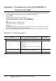
2 Conversion specifications of LS areas
The following indicates the conversion specifications of LS areas.
(1) The LS area described in the D script is also converted like the LS area set to the object.
Conversion source LS
area
Conversion destination
device
Description Remarks
LS0 to LS2031 GD0 to GD2031 Internal device Converted into device having the same
number as the LS area address.
LS2032 GS0 Common relay information
Appendix 2.9 Conversion
specifications of LS2032
LS2033 GS1 Base screen information
Appendix 2.9 Conversion
specifications of LS2033
LS2035 GS7 1-second binary counter ------
LS2036 GS8 Tag scan time ------
LS2038 GS10 Tag scan counter ------
LS2096 to LS8191 GD2096 to GD8191 Internal device Converted into device having the same
number as the LS area address.
Other LS areas
------ ------
Converted into the status where no devices
have been set.
3
4