
User's Manual


DIGITAL CONTROL INCORPORATED
DigiTrak Falcon
F2
Operator’s Manual 65
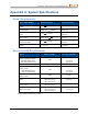
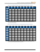
Appendix B: Receiver Screen Symbols
Symbol
Description
A
Attenuated Signal – The receiver automatically enters Attenuation mode when
locating at shallow depths of about 1 m or less to reduce excessive transmitter
signal strength. Displays at bottom left of roll indicator. Page 30
Globe Icon – Shown on the receiver startup screen, the number inside (shown
blank here) identifies the regional designation, which must match that on the
transmitter battery compartment. Page 7
Ground Level – Represents the ground for the HAG function, depth readings,
and the two-point calibration procedure. Page 31
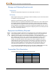
Locate Line –The locate line (LL) is found between the front and rear locate
points only after a reference lock has been obtained. May also include the
transmitter yaw angle in degrees. Page 31
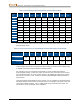
Locating Ball – Represents the front and rear locate points (FLP and RLP).
When the locate line appears, the locating ball will become a solid circle (ball)
representing the approximate locate point. Page 29
Locating Icon (Receiver) – Represents a bird’s-eye view of the receiver. The
square at the top of this icon is referred to as the “box” in the terms Ball-in-the-
Box™ and Line-in-the-Box locating. Page 29
Max mode – Max mode begins when the trigger is held longer that five seconds
during a depth reading. Page 31
Max mode timer – Provides a visual indication that Max mode is in effect
(trigger held). Replaces the roll/pitch update meter. Page 31
Pitch Assumed Zero – Indicates that since no pitch data is currently available,
the pitch is assumed to be zero for depth and distance calculations. Page 22
Receiver Battery Strength – Shows the remaining battery life of the receiver.
Appears above the main menu. When battery life is low, the icon will flash on
the Locate screen. Page 13
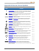
Receiver Icon – Indicates the position of the receiver relative to the ground for
the HAG function, depth readings, and the Target Steering function. Page 18
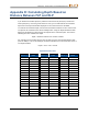
R
Reference Lock – Indicates a reference signal has been obtained for
displaying the locate line. Displays at the top of the Locate screen. Page 33
RO
Roll Offset – Indicates roll offset is enabled. Displays at bottom right of roll
indicator. Page 25
Roll/Pitch Update Meter – Shows the quality of data reception from the
transmitter (specifically, data rate). Five bars is the best signal. Fewer bars
indicates the receiver is in an area of interference or you are reaching the range
limit of the transmitter. Page 29