
User's Manual

DIGITAL CONTROL INCORPORATED
DigiTrak Falcon
F2
Operator’s Manual 35
Passive interference can reduce or increase the amount of signal received from the
transmitter, which results in incorrect depth readings, a completely blocked signal, or locates
in the wrong position. Examples of passive interference include metal objects such as pipes,
rebar, trench plate, chain-link fence, and vehicles. Two other examples are saltwater/salt
domes and conductive earth, such as iron ore. The receiver cannot test for the presence of
passive interference. Conducting a thorough site investigation prior to drilling is the best
method of identifying passive interference sources.
To familiarize yourself with the interference potential along your intended bore path, check for
background noise as discussed in the following section.
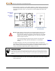
Warning A receiver cannot detect sources of passive interference; this can only
be accomplished with a visual inspection of the jobsite. A background
noise check can only find active interference.
I thought the Frequency Optimizer did all this for me?
The Frequency Optimizer finds the lowest-noise frequencies to use in each band. You choose which
bands to use and pair the transmitter. As best practice, now test those bands above ground to
ensure the receiver receives data for the intended portion of the bore. A good background noise
check is vital to a job free of interference surprises.
Checking for Interference
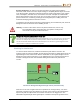
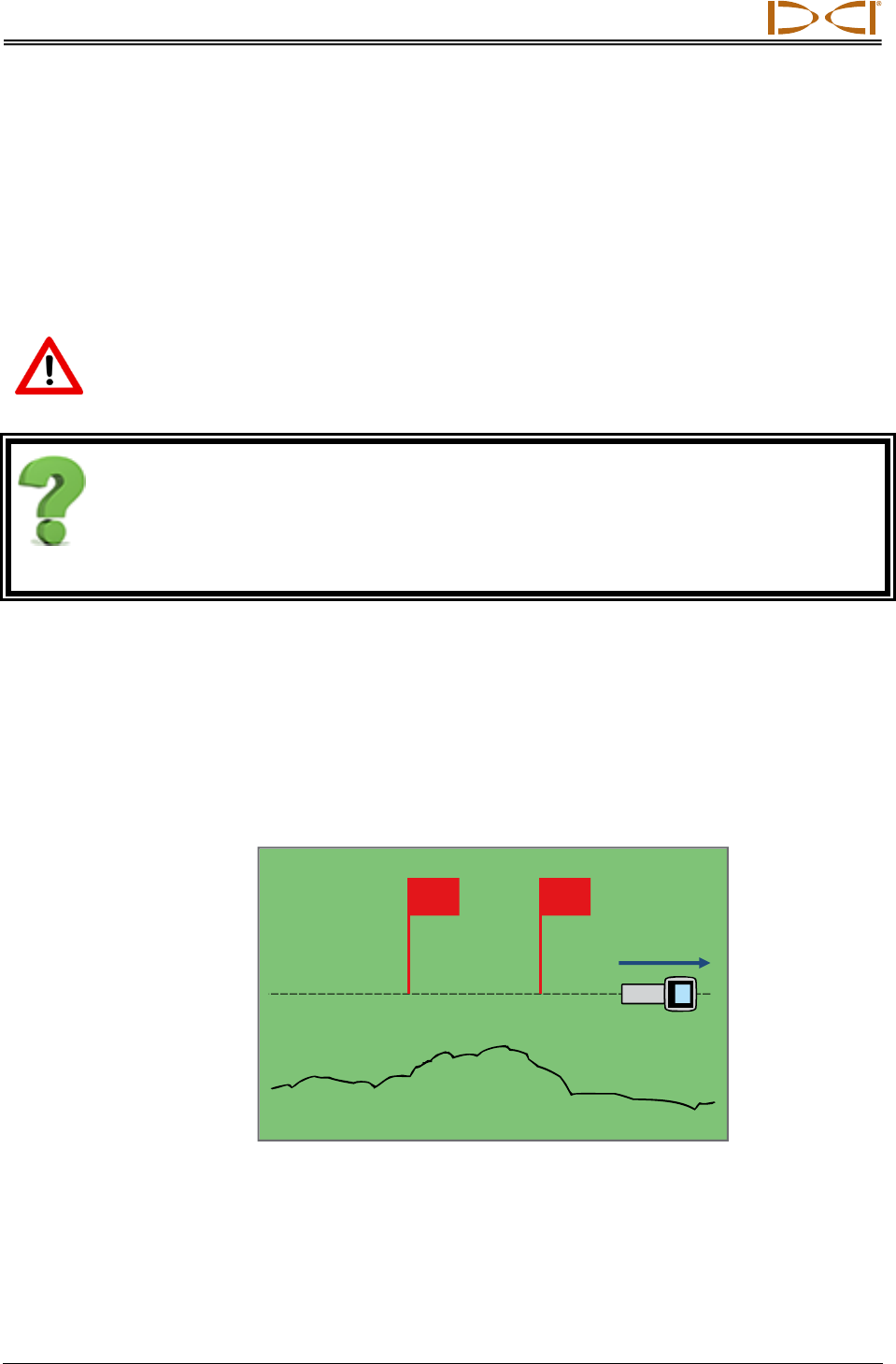
To check for active interference, walk the intended bore path with the receiver in the
frequency band you intend to drill with. Do this with the transmitter off, while taking note of the
signal strength on the Locate screen. With no transmitter on, this “signal strength” is in fact
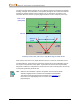
background noise (active interference). In the following figure, the red flag area denotes an
increase in background noise detected while walking the intended bore path with the
receiver.
One-Person Background Signal Strength Check (Transmitter Off)
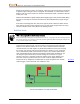
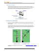
Now return to the area of highest interference (between the red flags above), turn on the
transmitter, and place it the same distance to the side of the receiver as the intended bore
depth. Verify that the roll/pitch data is consistent and correct in the flagged area. The
transmitter’s signal strength should generally be a minimum of 150 points greater than the
LL
Intended bore path
Background noise signal
Red flag area