
User's Manual

DIGITAL CONTROL INCORPORATED
DigiTrak Falcon
F2
Operator’s Manual 15
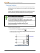
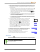
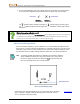
When frequency optimization is complete, the receiver shows the background noise
currently present in each of the nine frequency bands using an optimized selection of
the lowest-noise frequencies within each band. The shorter the bar on the graph, the
less interference present in that band.
Frequency Optimizer Results
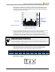
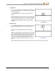
3. To measure noise readings from the entire intended bore, simply walk the bore with the
frequency optimization results displayed. As the receiver continues sampling
background noise, it marks the maximum noise reading of each band at the top of each
bar. Before choosing a frequency band, consider not only which bands remained
consistently low, but also which did not experience significant maximum noise readings.
Optimize as often as you want. You can't wear it out.
If you discover a significant source of active interference while walking the intended bore, select a
frequency band that was performing well prior to this point, then select and assign the second band
for the high-interference area. Or optimize again before assigning the second band. Optimize as
often as you want before assigning a band.
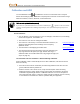
4. Click to move the selector to the band you want to use and hold briefly to select.
Typically this will be a band that remained at a low interference level and did not
experience high maximum noise readings while walking the bore path.
Band Number
7
11
16
20
25
29
34
38
43
Range in kHz
4.5–9.0
9.0–13.5
13.5–18
18–22.5
22.5–27
27–31.5
31.5–36
36–40.5
40.5–45
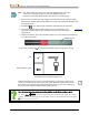
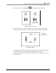
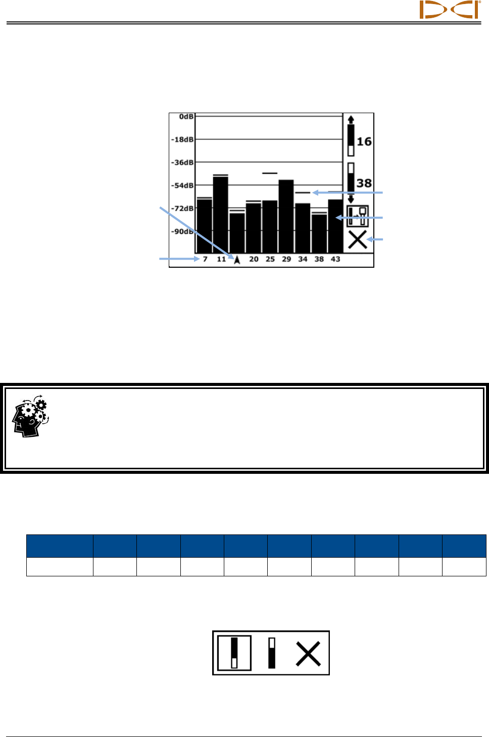
5. Select whether to assign this as the Up or Down band (the band the Tx powers on with
when facing Up or Down).
Up Down Cancel
Exit
Band selector
Maximum noise
reading
Median kHz of each band
Current optimized
noise readings