
User's Manual

DIGITAL CONTROL INCORPORATED
DigiTrak Falcon
™
F5
Operator’s Manual 75
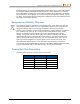
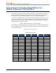
Symbol
Description
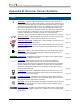
Pitch Assumed Zero – Indicates that since no pitch data is currently available,
the pitch is assumed to be zero for depth, predicted depth, and AGR
calculations. Page 40
Pressure – When using a fluid pressure transmitter, the number next to this
icon on the Locate screen indicates the pressure reading. If the pressure
reaches an over-limit condition (from 100–250 psi), the value will appear red.
When the pressure reaches the overload condition (over 250 psi), the value will
display as “+OL”. Page 61
Receiver Battery Strength – Shows the remaining battery life of the receiver
(shown 80% full here). Appears above the main menu. When battery life is low,
the icon will flash empty on the top left of the Locate screen. Page 14
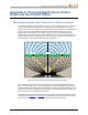
Receiver – Represents the position of the receiver relative to the ground for the
height-above-ground (HAG) function, depth readings, the two-point calibration
procedure, and the Target Steering function. Page 21
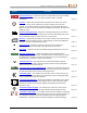
R
Reference Lock – Indicates a reference signal has been obtained for
displaying the locate line. Displays at the top of the Locate screen. Page 51
RO
Roll Offset – Indicates roll offset is enabled. Displays at bottom left of the roll
indicator. Page 25
Roll/Pitch Update Meter – Shows the quality of data reception from the
transmitter (specifically, data rate). A full bar indicates the best signal. A shorter
bar indicates the receiver is in an area of interference or you are reaching the
range limit of the transmitter, relative to interference. Page 39
Telemetry Channel – The channel used to communicate with the remote
display on the drill rig. Select whichever channel offers the best performance.
Select channel 0 to turn telemetry off. Page 24
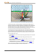
Transmitter Battery Strength/Drill Head – Depicts the remaining battery life of
the transmitter when alkaline batteries are used. Also represents the position of
the drill head relative to the receiver in the Depth screen. Page 40
Transmitter Pitch – The number next to this icon on the Locate screen is the
transmitter pitch angle. It is also the menu selection icon for changing the pitch
angle units between percent and degrees. Page 40
Transmitter Roll Indicator – Shows the transmitter’s roll position. A line points
to the roll position, and the roll value appears in the center of the clock. When
roll offset is enabled, the letters “RO” appear at the bottom left and the line
becomes a circle. Page 40
Transmitter Signal Strength – The number next to this icon on the Locate
screen is the transmitter signal strength. Maximum signal strength is 1200. Page 40
or
Transmitter Temperature – The number next to this icon shows the transmitter
temperature. An up or down arrow indicates the trend from the last reading. The
icon will glow red and flash when the transmitter becomes dangerously hot,
indicating the transmitter must be cooled immediately or it will be damaged. Page 68