
User's Manual

DIGITAL CONTROL INCORPORATED
46 DigiTrak Falcon
™
F5
Operator’s Manual
Suggestions for Dealing with Interference
If roll/pitch information becomes erratic or is lost while drilling or during a roll/pitch check (see
previous section), try one or more of the following:
Try Max mode.
Max Mode
Page 41
Move the receiver away from the interference source while staying
within range of the transmitter.
Off-Track Locating
Page 57
Physically separate the receiver from both passive and active
interference to reduce or eliminate interference-related problems.
Height-Above-Ground (HAG)
Page 21
Switch to the transmitter's other frequency band.
Changing Frequency Bands
Page 69
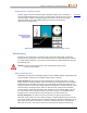
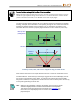
To overcome interference at the remote display, ensure the telemetry
antenna is vertical and that the front of the receiver is facing the
remote display. Set the receiver and remote display to use a different
telemetry channel. An optional extended-range telemetry antenna may
help overcome some forms of interference.
Never rely on the receiver as the sole means of communication between the receiver
operator and drill operator. In cases where data is not available on the remote display, both
operators must be able to communicate with each other.
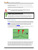
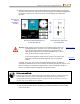
Warning In environments with extreme interference, the Falcon signal strength
on the receiver may begin to flash red along with a flashing red A
(Attenuation) at the top right of the roll indicator. This will also happen
when the locator is too close to the transmitter (less than two ft.). Any
depth, data, or locate information obtained when signal attenuation is in
effect should be considered an estimate.
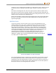
Locate Points (FLP & RLP) and Locate Line (LL)
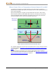
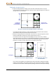
The Falcon F5 receiver locates the transmitter by detecting three specific places in the
transmitter’s magnetic field: the front locate point (FLP) ahead of the transmitter, the rear
locate point (RLP) behind the transmitter, and the locate line above the transmitter itself. The
locate points are indistinguishable from one another by the receiver as they represent similar
points in the transmitter’s field in front of and behind the transmitter (see Appendix C on
page 77 for more information about the transmitter’s magnetic field).
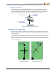
The locate line (LL) extends 90° to the left and right of the transmitter (perpendicular) when
the transmitter is at 0% pitch. It represents the location of the transmitter between the FLP
and RLP. If you think of the transmitter being the body of an airplane, its wings are the locate
line.