
User's Manual

DIGITAL CONTROL INCORPORATED
DigiTrak Falcon
™
F5
Operator’s Manual 45
reading of 175, the reading with the transmitter on at this location, and at a distance from the
receiver equal to the maximum intended bore depth, should be a minimum of 325 (175 +
150).
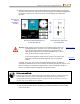
Areas where the background noise level is too high may make it difficult to obtain roll and
pitch data and accurate locates and depth readings. If the signal strength readings with the
transmitter on were not at least 150 points greater than the background noise level, conduct a
roll/pitch check as described in the following section.
Note that the transmitter’s signal strength will be slightly higher in this test than while drilling
because it is currently not encased in the drill head below ground, which will diminish the
signal strength slightly.
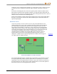
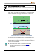
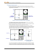
Roll/Pitch Check
At the exit of the bore, turn the receiver to face the entry and install batteries in the
paired transmitter to turn it on. Have a coworker hold the transmitter and stand beside
you. Walk together in parallel back toward the entry, keeping the receiver over the
bore path and the transmitter at a distance of 1 to 1.5 times the current intended bore
depth; where the bore is deeper, your coworker will be farther away. Periodically stop
and change the transmitter’s roll and pitch orientation so you can verify the speed and
accuracy of these readings on the receiver. It is good practice to also have a
coworker monitor the readings at the remote display at the same time. Note any
locations where the receiver or remote display information becomes erratic or
disappears. If roll/pitch data or signal strength become unstable, hold the trigger to
see if Max mode can stabilize the data.
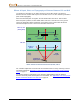
Max Mode
Page 41
Two-Person Roll/Pitch Test with Transmitter
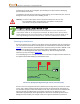
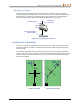
If the desired depth/data range in a red flag area is not sufficient, you may able to increase
the range by performing another frequency optimization here and pairing to a new band
specifically for use in this high-interference location. If you do this, check for interference in
the high-interference area again using the newly-optimized band. Use the other optimized
band (Up or Down) for the non-flagged portion of the bore.
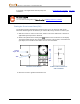
Intended bore path
Intended
depth
Red flag area