
User's Manual
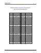
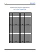

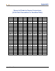
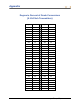

Table Of Contents
- Operator’s Manual
- Digital
- Control
- Incorporated
- DCI Headquarters 19625 62nd Ave. S., Suite B-103 Kent, Washington 98032 USA Tel 425 251 0559 / 800 288 3610 Fax 253 395 2800 E-mail DCI@digital-control.com www.digitrak.com
- Important Notice
- Safety Precautions and Warnings
- Safety Precautions and Warnings (Continued)
- _
- Introduction
- _
- Receiver
- Power On
- Toggle and Trigger Switches
- Speaker and Audible Tones
- Adjusting Screen Contrast
- Main Menu
- Locate Menu
- Set US Menu
- Low Fre/High Fre Menu
- Configure Menu
- Changing the Telemetry Channel
- 1-Point Calibration
- 2-Point Calibration (In-ground Calibration)
- Changing the Grade Mode
- Changing the Depth Measurement Mode
- Cold Screen / Normal Screen
- Tele Option A/B
- Locator DL / No Locator DL (Enabling and Disabling DataLog Menus)
- Set Roll / Unset Roll (Enabling and Disabling Roll Offset Function)
- Remote Display
- _
- Transmitter
- _
- Battery Charger
- _
- Locating
- _
- The Target Steering® Function
- _
- Cable System
- Cable System Components
- Non-DCI Supplies Required for Operating the Cable System
- Connecting Power Supply to Power Source and Cable Transmitter
- Grounding the Cable Transmitter
- Cable Transmitter On/Off
- Calibrating the Cable Transmitter
- Enabling the Roll Offset Function on the Remote Display
- Locating Using the Cable System
- Viewing Transmitter Depth or Predicted Depth
- Viewing Status of Cable System Power Source
- Target Steering Function Using the Cable System
- Troubleshooting
- _
- Appendix
- Depth Increase in Inches (Centimeters) per 6-foot (1.8 meter) Rod
- Depth Increase in Inches (Centimeters) per 10-foot (3-meter) Rod
- Depth Increase in Inches (Centimeters) per 15-foot (4.6-meter) Rod
- Percent of Grade to Degree Conversions (0.1% Pitch Transmitters or Sensitive Pitch)
- Degree to Percent of Grade Conversions (0.1% Pitch Transmitters)
- Calculating Depth Based on Distance Between FLP and RLP
- LIMITED WARRANTY

Appendix
Calculating Depth Based on
Distance Between FLP and RLP
It is possible to estimate the transmitter’s depth should the information displayed in the depth/distance
window become unreliable. This is only possible if the pitch and negative locate points are reliable and
the ground surface is level.
To estimate the transmitter’s depth, first measure the distance between the FLP and the RLP. The pitch
of the transmitter must also be reliably known. Using the Depth Estimation Table below, find the divider
that most closely corresponds to the transmitter’s pitch. Then use the following formula to estimate the
depth:
Divider
RLPandFLPbetweenDistance
Depth =
For example, if the transmitter’s pitch is 34% then the corresponding divider value (from the table) is 1.50.
In this example, the distance between the FLP and the RLP is 11.5 ft (3.5 m). The depth would be:
7.66
1.50
ft 11.5
Depth ==
ft or approximately 7.7 ft (2.35 m)
Depth Estimation Table
Pitch Divider Pitch Divider Pitch Divider Pitch Divider
0 1.41 26 1.47 52 1.62 78 1.84
2 1.41 28 1.48 54 1.63 80 1.85
4 1.42 30 1.48 56 1.64 82 1.87
6 1.42 32 1.49 58 1.66 84 1.89
8 1.42 34 1.50 60 1.68 86 1.91
10 1.42 36 1.51 62 1.69 88 1.93
12 1.43 38 1.52 64 1.71 90 1.96
14 1.43 40 1.54 66 1.73 92 1.98
16 1.43 42 1.55 68 1.74 94 2.00
18 1.44 44 1.56 70 1.76 96 2.02
20 1.45 46 1.57 72 1.78 98 2.04
22 1.45 48 1.59 74 1.80 100 2.06
24 1.46 50 1.60 76 1.82
DigiTrak
®
Eclipse
®
Operator’s Manual 73