
User's Manual
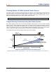

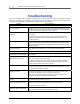
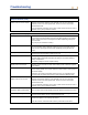
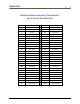
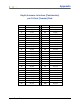

Table Of Contents
- Operator’s Manual
- Digital
- Control
- Incorporated
- DCI Headquarters 19625 62nd Ave. S., Suite B-103 Kent, Washington 98032 USA Tel 425 251 0559 / 800 288 3610 Fax 253 395 2800 E-mail DCI@digital-control.com www.digitrak.com
- Important Notice
- Safety Precautions and Warnings
- Safety Precautions and Warnings (Continued)
- _
- Introduction
- _
- Receiver
- Power On
- Toggle and Trigger Switches
- Speaker and Audible Tones
- Adjusting Screen Contrast
- Main Menu
- Locate Menu
- Set US Menu
- Low Fre/High Fre Menu
- Configure Menu
- Changing the Telemetry Channel
- 1-Point Calibration
- 2-Point Calibration (In-ground Calibration)
- Changing the Grade Mode
- Changing the Depth Measurement Mode
- Cold Screen / Normal Screen
- Tele Option A/B
- Locator DL / No Locator DL (Enabling and Disabling DataLog Menus)
- Set Roll / Unset Roll (Enabling and Disabling Roll Offset Function)
- Remote Display
- _
- Transmitter
- _
- Battery Charger
- _
- Locating
- _
- The Target Steering® Function
- _
- Cable System
- Cable System Components
- Non-DCI Supplies Required for Operating the Cable System
- Connecting Power Supply to Power Source and Cable Transmitter
- Grounding the Cable Transmitter
- Cable Transmitter On/Off
- Calibrating the Cable Transmitter
- Enabling the Roll Offset Function on the Remote Display
- Locating Using the Cable System
- Viewing Transmitter Depth or Predicted Depth
- Viewing Status of Cable System Power Source
- Target Steering Function Using the Cable System
- Troubleshooting
- _
- Appendix
- Depth Increase in Inches (Centimeters) per 6-foot (1.8 meter) Rod
- Depth Increase in Inches (Centimeters) per 10-foot (3-meter) Rod
- Depth Increase in Inches (Centimeters) per 15-foot (4.6-meter) Rod
- Percent of Grade to Degree Conversions (0.1% Pitch Transmitters or Sensitive Pitch)
- Degree to Percent of Grade Conversions (0.1% Pitch Transmitters)
- Calculating Depth Based on Distance Between FLP and RLP
- LIMITED WARRANTY

Cable System
Cable Transmitter On/Off
Before you can power up the remote display, you must ensure that the power supply, power source, and
cable transmitter are properly connected, as discussed in the previous sections. After properly connecting
the cable system, push the execute button to power up the remote display. Then select the Cable menu
option. This will enable the remote display to send power to the cable transmitter.
To turn the power off, press the toggle arrows on the remote display to select the Power Off option and
press the execute button. DCI recommends that you turn off the power to the cable transmitter prior to
working with the wire, such as when adding a new drill rod.
At the end of the drilling day it is necessary to stop power to the cable transmitter to conserve the battery
life of the power source. Use the Power Off menu option to turn off the power, then disconnect the power
source from the remote display.
Calibrating the Cable Transmitter
The cable transmitter is calibrated using the 1-point calibration procedure at a distance of 10 ft (3 m)—for
the proper procedure, refer to the 1-Point Calibration discussion under the “Configure Menu” in the
Receiver section. DCI recommends that you always check the depth readings at various locations against
a tape measure to confirm good calibration.
Enabling the Roll Offset Function on the Remote Display
The roll offset function is used when the drill bit (tool) and housing are two separate pieces and their roll
positions do not match when the tool is torqued-up to the housing. The roll offset function is an electronic
compensation to match the transmitter’s 12 o’clock position to the tool’s 12 o’clock position.
Enabling Roll Offset Function
To enable the roll offset function on the remote display:
1. Power up the remote display.
2. Select Configure from the remote display’s main menu and press the execute button.
3. Press the right arrow several times to select Set Roll, and press the execute button; this menu option
will change to Unset Roll.
The remote is now ready for you to set the roll offset number, which you should do if the transmitter’s 12
o’clock position does not match the tool’s 12 o’clock position.
Setting Roll Offset Number
To set the roll offset number:
1. Torque-up the tool to the housing.
2. Orient the tool to 12 o’clock.
3. Place the cable transmitter into the housing and power up using the Eclipse power supply.
DigiTrak
®
Eclipse
®
Operator’s Manual 61