
User's Manual
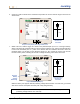
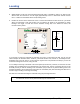
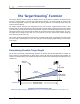
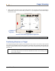
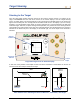
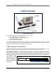
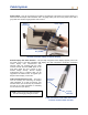
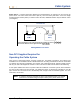
Table Of Contents
- Operator’s Manual
- Digital
- Control
- Incorporated
- DCI Headquarters 19625 62nd Ave. S., Suite B-103 Kent, Washington 98032 USA Tel 425 251 0559 / 800 288 3610 Fax 253 395 2800 E-mail DCI@digital-control.com www.digitrak.com
- Important Notice
- Safety Precautions and Warnings
- Safety Precautions and Warnings (Continued)
- _
- Introduction
- _
- Receiver
- Power On
- Toggle and Trigger Switches
- Speaker and Audible Tones
- Adjusting Screen Contrast
- Main Menu
- Locate Menu
- Set US Menu
- Low Fre/High Fre Menu
- Configure Menu
- Changing the Telemetry Channel
- 1-Point Calibration
- 2-Point Calibration (In-ground Calibration)
- Changing the Grade Mode
- Changing the Depth Measurement Mode
- Cold Screen / Normal Screen
- Tele Option A/B
- Locator DL / No Locator DL (Enabling and Disabling DataLog Menus)
- Set Roll / Unset Roll (Enabling and Disabling Roll Offset Function)
- Remote Display
- _
- Transmitter
- _
- Battery Charger
- _
- Locating
- _
- The Target Steering® Function
- _
- Cable System
- Cable System Components
- Non-DCI Supplies Required for Operating the Cable System
- Connecting Power Supply to Power Source and Cable Transmitter
- Grounding the Cable Transmitter
- Cable Transmitter On/Off
- Calibrating the Cable Transmitter
- Enabling the Roll Offset Function on the Remote Display
- Locating Using the Cable System
- Viewing Transmitter Depth or Predicted Depth
- Viewing Status of Cable System Power Source
- Target Steering Function Using the Cable System
- Troubleshooting
- _
- Appendix
- Depth Increase in Inches (Centimeters) per 6-foot (1.8 meter) Rod
- Depth Increase in Inches (Centimeters) per 10-foot (3-meter) Rod
- Depth Increase in Inches (Centimeters) per 15-foot (4.6-meter) Rod
- Percent of Grade to Degree Conversions (0.1% Pitch Transmitters or Sensitive Pitch)
- Degree to Percent of Grade Conversions (0.1% Pitch Transmitters)
- Calculating Depth Based on Distance Between FLP and RLP
- LIMITED WARRANTY

Cable System
Power Source – Lead-acid automotive batteries that supply between 12 and 28 V DC are used for the
power source. For bores shorter than 1000 ft (305 m), one 12-V battery will suffice. If the bore length
increases beyond 1000 ft (305 m) or advance rates decrease, additional batteries may be added in series
(see diagram).
Connect batteries in the order shown by the numbers in circles: 1 , 2 , 3 , 4
Disconnect batteries in the opposite order: 4 , 3 , 2 , 1
12-Volt
Battery
–
+
12-Volt
Battery
–
+
–
+
12–28 Volts DC
4
3
2 1
Adding Batteries in Series
Non-DCI Supplies Required for
Operating the Cable System
Items such as compression fittings, 10-gauge copper wire, heat shrink, butt splices, and collector ring
assemblies are not available from DCI. Drill manufacturers or tooling manufacturers will have information
on collector ring (slip-ring) assemblies, mud swivels, and compression fittings. Electrical supply houses
will carry the rest of the equipment needed to connect the wires as drill rods are added to the drill string.
A new option available from DCI is a product called the CableLink
®
connection system, which eliminates
the need for butt splices and heat shrinks. The CableLink system is permanently installed into the drill
pipe, and the wire connection occurs automatically when the pipe ends are threaded together. For more
information, contact DCI.
NOTE: A multimeter should be available for power testing/troubleshooting. For detailed
instructions on troubleshooting the Eclipse cable system, please contact DCI.
DigiTrak
®
Eclipse
®
Operator’s Manual 59