
User's Manual
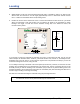
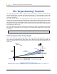
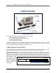
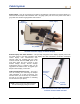
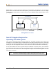
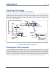
Table Of Contents
- Operator’s Manual
- Digital
- Control
- Incorporated
- DCI Headquarters 19625 62nd Ave. S., Suite B-103 Kent, Washington 98032 USA Tel 425 251 0559 / 800 288 3610 Fax 253 395 2800 E-mail DCI@digital-control.com www.digitrak.com
- Important Notice
- Safety Precautions and Warnings
- Safety Precautions and Warnings (Continued)
- _
- Introduction
- _
- Receiver
- Power On
- Toggle and Trigger Switches
- Speaker and Audible Tones
- Adjusting Screen Contrast
- Main Menu
- Locate Menu
- Set US Menu
- Low Fre/High Fre Menu
- Configure Menu
- Changing the Telemetry Channel
- 1-Point Calibration
- 2-Point Calibration (In-ground Calibration)
- Changing the Grade Mode
- Changing the Depth Measurement Mode
- Cold Screen / Normal Screen
- Tele Option A/B
- Locator DL / No Locator DL (Enabling and Disabling DataLog Menus)
- Set Roll / Unset Roll (Enabling and Disabling Roll Offset Function)
- Remote Display
- _
- Transmitter
- _
- Battery Charger
- _
- Locating
- _
- The Target Steering® Function
- _
- Cable System
- Cable System Components
- Non-DCI Supplies Required for Operating the Cable System
- Connecting Power Supply to Power Source and Cable Transmitter
- Grounding the Cable Transmitter
- Cable Transmitter On/Off
- Calibrating the Cable Transmitter
- Enabling the Roll Offset Function on the Remote Display
- Locating Using the Cable System
- Viewing Transmitter Depth or Predicted Depth
- Viewing Status of Cable System Power Source
- Target Steering Function Using the Cable System
- Troubleshooting
- _
- Appendix
- Depth Increase in Inches (Centimeters) per 6-foot (1.8 meter) Rod
- Depth Increase in Inches (Centimeters) per 10-foot (3-meter) Rod
- Depth Increase in Inches (Centimeters) per 15-foot (4.6-meter) Rod
- Percent of Grade to Degree Conversions (0.1% Pitch Transmitters or Sensitive Pitch)
- Degree to Percent of Grade Conversions (0.1% Pitch Transmitters)
- Calculating Depth Based on Distance Between FLP and RLP
- LIMITED WARRANTY

DIGITAL CONTROL INCORPORATED
Cable System
Remote
Display
Power
Supply
Cable
Transmitter
Extraction/
Insertion Tool
Eclipse Cable System
The Eclipse cable system is designed specifically for bores that:
¾ Have depths in excess of 50 ft (15.2 m).
¾ Have lengths that require several days to drill.
¾ Do not allow walkover locating.
¾ Are in high-interference areas.
The depth and locating ranges of the Eclipse cable system are both approximately 80 ft (24.4 m). These
ranges are dependent upon environmental conditions and characteristics of the housing. Depth and
lateral location information is tracked using the Eclipse receiver.
Cable System Components
The Eclipse cable system consists of four main components (cable transmitter, power supply, remote
display, and cable extraction/insertion tool) and a power source, which are described below.
Eclipse Cable Transmitter – This transmitter measures 19.00 in. (482.6 mm) in length by 1.25 in. (31.8
mm) in diameter. It requires a special rear-load housing with an end plug that allows the transmitter’s
cable to exit the housing. The end plug requires a compression fitting to seal the transmitter from the
drilling fluid. The housing must also have at least three slots equally spaced around the circumference of
the transmitter that
measure 9.0 in. (229
mm) in length and at
least 1/16 or 0.0625 in.
(1.6 mm) in width (see
figure) for proper sig-
nal emission.
Wireline End Index Cap End
Slot Position
Slot Length
9.0 in. (229 mm)
2.5 in.
(64 mm)
Slot Geometry on Cable Transmitters
DigiTrak
®
Eclipse
®
Operator’s Manual 57