
User's Manual
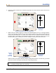
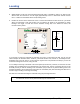
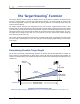
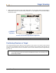
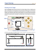
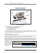
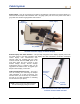
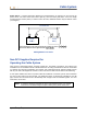
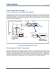
Table Of Contents
- Operator’s Manual
- Digital
- Control
- Incorporated
- DCI Headquarters 19625 62nd Ave. S., Suite B-103 Kent, Washington 98032 USA Tel 425 251 0559 / 800 288 3610 Fax 253 395 2800 E-mail DCI@digital-control.com www.digitrak.com
- Important Notice
- Safety Precautions and Warnings
- Safety Precautions and Warnings (Continued)
- _
- Introduction
- _
- Receiver
- Power On
- Toggle and Trigger Switches
- Speaker and Audible Tones
- Adjusting Screen Contrast
- Main Menu
- Locate Menu
- Set US Menu
- Low Fre/High Fre Menu
- Configure Menu
- Changing the Telemetry Channel
- 1-Point Calibration
- 2-Point Calibration (In-ground Calibration)
- Changing the Grade Mode
- Changing the Depth Measurement Mode
- Cold Screen / Normal Screen
- Tele Option A/B
- Locator DL / No Locator DL (Enabling and Disabling DataLog Menus)
- Set Roll / Unset Roll (Enabling and Disabling Roll Offset Function)
- Remote Display
- _
- Transmitter
- _
- Battery Charger
- _
- Locating
- _
- The Target Steering® Function
- _
- Cable System
- Cable System Components
- Non-DCI Supplies Required for Operating the Cable System
- Connecting Power Supply to Power Source and Cable Transmitter
- Grounding the Cable Transmitter
- Cable Transmitter On/Off
- Calibrating the Cable Transmitter
- Enabling the Roll Offset Function on the Remote Display
- Locating Using the Cable System
- Viewing Transmitter Depth or Predicted Depth
- Viewing Status of Cable System Power Source
- Target Steering Function Using the Cable System
- Troubleshooting
- _
- Appendix
- Depth Increase in Inches (Centimeters) per 6-foot (1.8 meter) Rod
- Depth Increase in Inches (Centimeters) per 10-foot (3-meter) Rod
- Depth Increase in Inches (Centimeters) per 15-foot (4.6-meter) Rod
- Percent of Grade to Degree Conversions (0.1% Pitch Transmitters or Sensitive Pitch)
- Degree to Percent of Grade Conversions (0.1% Pitch Transmitters)
- Calculating Depth Based on Distance Between FLP and RLP
- LIMITED WARRANTY

Target Steering
Steering to the Target
Once the target depth number has been entered on the receiver and the receiver is in position as the
target, select Remote from the main menu screen on the remote display to see the Target Steering
screen, as shown below. The steering indicator in this case shows that the drill head is to the left and too
high for the intended path. The steering indicator should be dead center in the display if you are correctly
heading to your programmed target depth. A steering command of 4 o’clock would bring the drill head
toward the target. Note that, for quick viewing and interpretation, the pointed end of the steering indicator
corresponds to the clock position of the head. The horizontal distance from the drill head to the receiver is
indicated at the bottom left part of the display. At the bottom right, the current depth of the drill head is
indicated.
CH:B1
75
°
F
7.5
%
Steering
Indicator
Horizontal
Distance
Current
Depth
Target Steering Screen on Remote Display
A side view of the position of the Eclipse receiver and of the transmitter is shown below on the left. An
end view of the same setup is shown on the right.
20
’
4
”
4
’
6
”
5
’
6
”
5
’
6
”
4
’
6
”
Transmitter
Back of
Receiver
Actual Position
of Transmitter
Target
Target
Surface of
Ground
Side and End Views Showing Positions of Receiver, Transmitter, and Target
56 DigiTrak
®
Eclipse
®
Operator’s Manual