
User's Manual
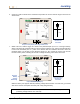
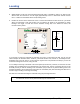
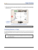
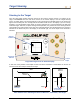
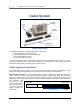
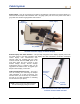
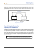
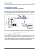
Table Of Contents
- Operator’s Manual
- Digital
- Control
- Incorporated
- DCI Headquarters 19625 62nd Ave. S., Suite B-103 Kent, Washington 98032 USA Tel 425 251 0559 / 800 288 3610 Fax 253 395 2800 E-mail DCI@digital-control.com www.digitrak.com
- Important Notice
- Safety Precautions and Warnings
- Safety Precautions and Warnings (Continued)
- _
- Introduction
- _
- Receiver
- Power On
- Toggle and Trigger Switches
- Speaker and Audible Tones
- Adjusting Screen Contrast
- Main Menu
- Locate Menu
- Set US Menu
- Low Fre/High Fre Menu
- Configure Menu
- Changing the Telemetry Channel
- 1-Point Calibration
- 2-Point Calibration (In-ground Calibration)
- Changing the Grade Mode
- Changing the Depth Measurement Mode
- Cold Screen / Normal Screen
- Tele Option A/B
- Locator DL / No Locator DL (Enabling and Disabling DataLog Menus)
- Set Roll / Unset Roll (Enabling and Disabling Roll Offset Function)
- Remote Display
- _
- Transmitter
- _
- Battery Charger
- _
- Locating
- _
- The Target Steering® Function
- _
- Cable System
- Cable System Components
- Non-DCI Supplies Required for Operating the Cable System
- Connecting Power Supply to Power Source and Cable Transmitter
- Grounding the Cable Transmitter
- Cable Transmitter On/Off
- Calibrating the Cable Transmitter
- Enabling the Roll Offset Function on the Remote Display
- Locating Using the Cable System
- Viewing Transmitter Depth or Predicted Depth
- Viewing Status of Cable System Power Source
- Target Steering Function Using the Cable System
- Troubleshooting
- _
- Appendix
- Depth Increase in Inches (Centimeters) per 6-foot (1.8 meter) Rod
- Depth Increase in Inches (Centimeters) per 10-foot (3-meter) Rod
- Depth Increase in Inches (Centimeters) per 15-foot (4.6-meter) Rod
- Percent of Grade to Degree Conversions (0.1% Pitch Transmitters or Sensitive Pitch)
- Degree to Percent of Grade Conversions (0.1% Pitch Transmitters)
- Calculating Depth Based on Distance Between FLP and RLP
- LIMITED WARRANTY

Locating
8. While standing on the FLP and facing back toward the drill, it is possible to “sight in” or align the FLP
with the RLP. This axis line is at a 90° angle (perpendicular) to the LL. Where this axis line crosses
the LL is where the transmitter will be found, below ground.
9. Position the receiver at the intersection of the LL and the line between the RLP and FLP—you will be
above the transmitter. From this location you can observe the depth of the transmitter by simply
holding in the trigger. You will also see the ultrasonic setting and, in the bottom left corner, the
receiver’s battery status.
FLP
RLP
LL
Actual Position of
Receiver and
Transmitter
Eclipse Depth Display
15.8
SH
7.5
%
CH:B1
75
°
F
456.5
R
If you choose to locate the transmitter by standing out in front of it and facing the drill, you can use the
same technique as described above. However, you will first find the FLP, then the LL, and finally the RLP.
Remember that you must “lock in” on the reference signal at the FLP (instead of the RLP) if you use the
method of locating from the front, facing the drill.
It is not always necessary to find both of the locate points (RLP and FLP). However, for the most accurate
locating, DCI recommends that you find both the FLP and the RLP. The line connecting the FLP to the
RLP will provide you with the heading of the transmitter (tool) as well as its position below ground. The
heading information can be particularly useful when the transmitter (tool) hits something that deflects it to
the left or right, resulting in a change of heading.
DCI does not recommend locating the transmitter using the peak signal method.
NOTE: It is very important to position the receiver accurately. The depth reading can be in-
accurate if the receiver is not positioned directly over the drill head.
52 DigiTrak
®
Eclipse
®
Operator’s Manual