
User's Manual
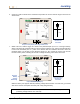
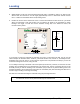
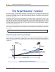
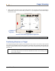
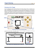
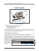
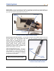
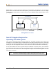
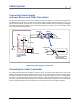
Table Of Contents
- Operator’s Manual
- Digital
- Control
- Incorporated
- DCI Headquarters 19625 62nd Ave. S., Suite B-103 Kent, Washington 98032 USA Tel 425 251 0559 / 800 288 3610 Fax 253 395 2800 E-mail DCI@digital-control.com www.digitrak.com
- Important Notice
- Safety Precautions and Warnings
- Safety Precautions and Warnings (Continued)
- _
- Introduction
- _
- Receiver
- Power On
- Toggle and Trigger Switches
- Speaker and Audible Tones
- Adjusting Screen Contrast
- Main Menu
- Locate Menu
- Set US Menu
- Low Fre/High Fre Menu
- Configure Menu
- Changing the Telemetry Channel
- 1-Point Calibration
- 2-Point Calibration (In-ground Calibration)
- Changing the Grade Mode
- Changing the Depth Measurement Mode
- Cold Screen / Normal Screen
- Tele Option A/B
- Locator DL / No Locator DL (Enabling and Disabling DataLog Menus)
- Set Roll / Unset Roll (Enabling and Disabling Roll Offset Function)
- Remote Display
- _
- Transmitter
- _
- Battery Charger
- _
- Locating
- _
- The Target Steering® Function
- _
- Cable System
- Cable System Components
- Non-DCI Supplies Required for Operating the Cable System
- Connecting Power Supply to Power Source and Cable Transmitter
- Grounding the Cable Transmitter
- Cable Transmitter On/Off
- Calibrating the Cable Transmitter
- Enabling the Roll Offset Function on the Remote Display
- Locating Using the Cable System
- Viewing Transmitter Depth or Predicted Depth
- Viewing Status of Cable System Power Source
- Target Steering Function Using the Cable System
- Troubleshooting
- _
- Appendix
- Depth Increase in Inches (Centimeters) per 6-foot (1.8 meter) Rod
- Depth Increase in Inches (Centimeters) per 10-foot (3-meter) Rod
- Depth Increase in Inches (Centimeters) per 15-foot (4.6-meter) Rod
- Percent of Grade to Degree Conversions (0.1% Pitch Transmitters or Sensitive Pitch)
- Degree to Percent of Grade Conversions (0.1% Pitch Transmitters)
- Calculating Depth Based on Distance Between FLP and RLP
- LIMITED WARRANTY

Locating
6. Continue to walk out ahead of the transmitter and position the receiver until the target is in the box as
shown below.
FLP
RLP
LL
Actual Position of
Receiver and
Transmitter
Eclipse Locating Display with Target in Box at FLP
SH
7.5
%
CH:B1
75
°
F
433.5
7. While at the FLP, hold the trigger in to observe the predicted depth (11 ft 8 in. in the figure below),
which is the depth the transmitter will be at when it passes under the FLP, and the horizontal distance
in front of the transmitter (8 ft 7 in.), which is the distance that the transmitter will travel to reach the
predicted depth. You will also see the ultrasonic setting (1 ft 10 in.) below the receiver icon and the
receiver’s battery status, including the amount of voltage remaining, in the bottom left corner.
FLP
RLP
LL
Actual Position of
Receiver and
Transmitter
Eclipse Predicted Depth Display
15.8
433.5
SH
7.5
%
CH:B1
75
°
F
R
When the battery icon appears half full (remaining voltage will be between 14.2 and 14.8), you should
shut off the receiver and replace the battery with a fully charged battery.
NOTE: You should replace the receiver battery when the receiver battery icon appears half full
(remaining voltage between 14.2 and 14.8).
Receiver
Battery
Voltage
Remaining
DigiTrak
®
Eclipse
®
Operator’s Manual 51