
User's Manual

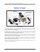
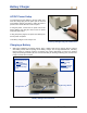

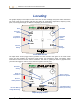
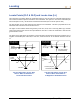
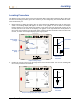
Table Of Contents
- Operator’s Manual
- Digital
- Control
- Incorporated
- DCI Headquarters 19625 62nd Ave. S., Suite B-103 Kent, Washington 98032 USA Tel 425 251 0559 / 800 288 3610 Fax 253 395 2800 E-mail DCI@digital-control.com www.digitrak.com
- Important Notice
- Safety Precautions and Warnings
- Safety Precautions and Warnings (Continued)
- _
- Introduction
- _
- Receiver
- Power On
- Toggle and Trigger Switches
- Speaker and Audible Tones
- Adjusting Screen Contrast
- Main Menu
- Locate Menu
- Set US Menu
- Low Fre/High Fre Menu
- Configure Menu
- Changing the Telemetry Channel
- 1-Point Calibration
- 2-Point Calibration (In-ground Calibration)
- Changing the Grade Mode
- Changing the Depth Measurement Mode
- Cold Screen / Normal Screen
- Tele Option A/B
- Locator DL / No Locator DL (Enabling and Disabling DataLog Menus)
- Set Roll / Unset Roll (Enabling and Disabling Roll Offset Function)
- Remote Display
- _
- Transmitter
- _
- Battery Charger
- _
- Locating
- _
- The Target Steering® Function
- _
- Cable System
- Cable System Components
- Non-DCI Supplies Required for Operating the Cable System
- Connecting Power Supply to Power Source and Cable Transmitter
- Grounding the Cable Transmitter
- Cable Transmitter On/Off
- Calibrating the Cable Transmitter
- Enabling the Roll Offset Function on the Remote Display
- Locating Using the Cable System
- Viewing Transmitter Depth or Predicted Depth
- Viewing Status of Cable System Power Source
- Target Steering Function Using the Cable System
- Troubleshooting
- _
- Appendix
- Depth Increase in Inches (Centimeters) per 6-foot (1.8 meter) Rod
- Depth Increase in Inches (Centimeters) per 10-foot (3-meter) Rod
- Depth Increase in Inches (Centimeters) per 15-foot (4.6-meter) Rod
- Percent of Grade to Degree Conversions (0.1% Pitch Transmitters or Sensitive Pitch)
- Degree to Percent of Grade Conversions (0.1% Pitch Transmitters)
- Calculating Depth Based on Distance Between FLP and RLP
- LIMITED WARRANTY

Locating
NOTE: To ensure you are over the RLP, you can rotate the receiver 360°, being careful to
keep the receiver display at the center of the rotation. The target should stay in the
same position in the box on the receiver’s display. If it does not, then the receiver’s
antenna may be malfunctioning—you should contact DCI Customer Service, 800-288-
3610 or 425-251-0559, for assistance.
3. Hold in the trigger for at least one second to “lock in” on the reference signal (you will see the “R”
symbol appear at the top of the display until you release the trigger).
4. Continue walking away from the drill and toward the transmitter. You will see the target move from the
box to the bottom of the screen, and then it will quickly appear at the top of the screen. You will then
see the LL appear as pictured below.
FLP
RLP
LL
Actual Position of
Receiver and
Transmitter
Eclipse Locating Display with Operator Approaching LL
456.5
SH
7.5
%
CH:B1
75
°
F
5. Position the receiver until the LL lines up with the two horizontal cross hairs. You are now standing on
the LL. To determine the exact lateral position of the transmitter, you will need to find the FLP.
FLP
RLP
LL
Actual Position of
Receiver and
Transmitter
Eclipse Locating Display with Operator at LL
459
SH
7.5
%
CH:B1
75
°
F
459
50 DigiTrak
®
Eclipse
®
Operator’s Manual