
User's Manual

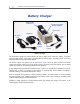
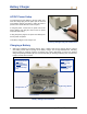

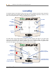
Table Of Contents
- Operator’s Manual
- Digital
- Control
- Incorporated
- DCI Headquarters 19625 62nd Ave. S., Suite B-103 Kent, Washington 98032 USA Tel 425 251 0559 / 800 288 3610 Fax 253 395 2800 E-mail DCI@digital-control.com www.digitrak.com
- Important Notice
- Safety Precautions and Warnings
- Safety Precautions and Warnings (Continued)
- _
- Introduction
- _
- Receiver
- Power On
- Toggle and Trigger Switches
- Speaker and Audible Tones
- Adjusting Screen Contrast
- Main Menu
- Locate Menu
- Set US Menu
- Low Fre/High Fre Menu
- Configure Menu
- Changing the Telemetry Channel
- 1-Point Calibration
- 2-Point Calibration (In-ground Calibration)
- Changing the Grade Mode
- Changing the Depth Measurement Mode
- Cold Screen / Normal Screen
- Tele Option A/B
- Locator DL / No Locator DL (Enabling and Disabling DataLog Menus)
- Set Roll / Unset Roll (Enabling and Disabling Roll Offset Function)
- Remote Display
- _
- Transmitter
- _
- Battery Charger
- _
- Locating
- _
- The Target Steering® Function
- _
- Cable System
- Cable System Components
- Non-DCI Supplies Required for Operating the Cable System
- Connecting Power Supply to Power Source and Cable Transmitter
- Grounding the Cable Transmitter
- Cable Transmitter On/Off
- Calibrating the Cable Transmitter
- Enabling the Roll Offset Function on the Remote Display
- Locating Using the Cable System
- Viewing Transmitter Depth or Predicted Depth
- Viewing Status of Cable System Power Source
- Target Steering Function Using the Cable System
- Troubleshooting
- _
- Appendix
- Depth Increase in Inches (Centimeters) per 6-foot (1.8 meter) Rod
- Depth Increase in Inches (Centimeters) per 10-foot (3-meter) Rod
- Depth Increase in Inches (Centimeters) per 15-foot (4.6-meter) Rod
- Percent of Grade to Degree Conversions (0.1% Pitch Transmitters or Sensitive Pitch)
- Degree to Percent of Grade Conversions (0.1% Pitch Transmitters)
- Calculating Depth Based on Distance Between FLP and RLP
- LIMITED WARRANTY

Locating
Locate Points (FLP & RLP) and Locate Line (LL)
Three positions or locations within the transmitter’s field are used to locate the transmitter below ground.
Two of these locations represent extensions of the transmitter. One point is in front of the transmitter (the
front locate point or FLP), and the other is behind the transmitter (the rear locate point or RLP).
The third location is a line that represents the position of the transmitter. This
line is perpendicular to the
transmitter and is referred to as the locate line or LL.
The figure on the left below shows the geometry of the FLP, RLP, and LL from top (bird’s-eye) and side
views. Note how the RLP and FLP are equal distances from the LL when the transmitter is level and the
ground surface is level.
The figure on the right shows the geometry of the locate points and locate line when the transmitter is at a
negative or downward pitch. Note how, in this case, the RLP and FLP are at different distances from the
LL.
RLP
FLP
Transmitter
LL
RLP
FLP
Ground
Surface
Transmitter
Bird's-Eye View
(Looking Down)
Side View
Axis Line
LL
Drill
Drill
Ground
Surface
Bird's
-
Eye View
(Looking Down)
Side View
Axis Line
FLP
Transmitter (Negative
or Downward Pitch)
RLP
RLP FLP
LL
Transmitter (Negative
or Downward Pitch)
LL
Drill
Drill
Top and Side Views of FLP, RLP, Top and Side Views of FLP, RLP,
and LL When Transmitter Is and LL When Transmitter Is
Level with the Ground at Negative or Downward Pitch
48 DigiTrak
®
Eclipse
®
Operator’s Manual