
User's Manual

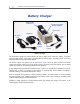
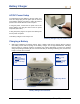

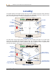
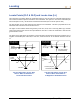
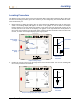
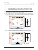
Table Of Contents
- Operator’s Manual
- Digital
- Control
- Incorporated
- DCI Headquarters 19625 62nd Ave. S., Suite B-103 Kent, Washington 98032 USA Tel 425 251 0559 / 800 288 3610 Fax 253 395 2800 E-mail DCI@digital-control.com www.digitrak.com
- Important Notice
- Safety Precautions and Warnings
- Safety Precautions and Warnings (Continued)
- _
- Introduction
- _
- Receiver
- Power On
- Toggle and Trigger Switches
- Speaker and Audible Tones
- Adjusting Screen Contrast
- Main Menu
- Locate Menu
- Set US Menu
- Low Fre/High Fre Menu
- Configure Menu
- Changing the Telemetry Channel
- 1-Point Calibration
- 2-Point Calibration (In-ground Calibration)
- Changing the Grade Mode
- Changing the Depth Measurement Mode
- Cold Screen / Normal Screen
- Tele Option A/B
- Locator DL / No Locator DL (Enabling and Disabling DataLog Menus)
- Set Roll / Unset Roll (Enabling and Disabling Roll Offset Function)
- Remote Display
- _
- Transmitter
- _
- Battery Charger
- _
- Locating
- _
- The Target Steering® Function
- _
- Cable System
- Cable System Components
- Non-DCI Supplies Required for Operating the Cable System
- Connecting Power Supply to Power Source and Cable Transmitter
- Grounding the Cable Transmitter
- Cable Transmitter On/Off
- Calibrating the Cable Transmitter
- Enabling the Roll Offset Function on the Remote Display
- Locating Using the Cable System
- Viewing Transmitter Depth or Predicted Depth
- Viewing Status of Cable System Power Source
- Target Steering Function Using the Cable System
- Troubleshooting
- _
- Appendix
- Depth Increase in Inches (Centimeters) per 6-foot (1.8 meter) Rod
- Depth Increase in Inches (Centimeters) per 10-foot (3-meter) Rod
- Depth Increase in Inches (Centimeters) per 15-foot (4.6-meter) Rod
- Percent of Grade to Degree Conversions (0.1% Pitch Transmitters or Sensitive Pitch)
- Degree to Percent of Grade Conversions (0.1% Pitch Transmitters)
- Calculating Depth Based on Distance Between FLP and RLP
- LIMITED WARRANTY

Battery Charger
AC/DC Power Setup
Inserting Charger Plug into Power Port
To install either the AC adapter or the DC power cord,
insert the charger plug into the power port on the back
of the battery charger (see photo to right) and rotate a
quarter turn in either direction to lock it in place.
If using AC power, connect the AC power cord to the
power adapter, then plug the cord into the AC power
receptacle (wall outlet).
If using DC power, plug the DC power cord directly into
the DC power receptacle.
Your battery charger is now ready to use.
Charging a Battery
1. With power supplied to the battery charger, place a battery pack into the charger with the terminal
end making contact with the springs in the battery charger. The red light will illuminate, indicating
that the battery is charging. However, the battery may require discharging to remove any residual
charge and prolong the battery life; DCI recommends that you discharge a battery pack, as instructed
in step 2, at least once a month.
Red Light:
–
Solid indicates unit
is charging.
– Blinking indicates
low-voltage battery
or power interrup-
tion.
Green Light:
–
Solid indicates
battery is fully
charged.
–
Blinking indicates
battery is being
discharged.
Discharge Button
Charge Button
Serial Numbe
r
Battery Charger Control Panel
44 DigiTrak
®
Eclipse
®
Operator’s Manual