
User's Manual

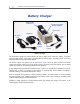
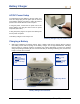

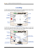
Table Of Contents
- Operator’s Manual
- Digital
- Control
- Incorporated
- DCI Headquarters 19625 62nd Ave. S., Suite B-103 Kent, Washington 98032 USA Tel 425 251 0559 / 800 288 3610 Fax 253 395 2800 E-mail DCI@digital-control.com www.digitrak.com
- Important Notice
- Safety Precautions and Warnings
- Safety Precautions and Warnings (Continued)
- _
- Introduction
- _
- Receiver
- Power On
- Toggle and Trigger Switches
- Speaker and Audible Tones
- Adjusting Screen Contrast
- Main Menu
- Locate Menu
- Set US Menu
- Low Fre/High Fre Menu
- Configure Menu
- Changing the Telemetry Channel
- 1-Point Calibration
- 2-Point Calibration (In-ground Calibration)
- Changing the Grade Mode
- Changing the Depth Measurement Mode
- Cold Screen / Normal Screen
- Tele Option A/B
- Locator DL / No Locator DL (Enabling and Disabling DataLog Menus)
- Set Roll / Unset Roll (Enabling and Disabling Roll Offset Function)
- Remote Display
- _
- Transmitter
- _
- Battery Charger
- _
- Locating
- _
- The Target Steering® Function
- _
- Cable System
- Cable System Components
- Non-DCI Supplies Required for Operating the Cable System
- Connecting Power Supply to Power Source and Cable Transmitter
- Grounding the Cable Transmitter
- Cable Transmitter On/Off
- Calibrating the Cable Transmitter
- Enabling the Roll Offset Function on the Remote Display
- Locating Using the Cable System
- Viewing Transmitter Depth or Predicted Depth
- Viewing Status of Cable System Power Source
- Target Steering Function Using the Cable System
- Troubleshooting
- _
- Appendix
- Depth Increase in Inches (Centimeters) per 6-foot (1.8 meter) Rod
- Depth Increase in Inches (Centimeters) per 10-foot (3-meter) Rod
- Depth Increase in Inches (Centimeters) per 15-foot (4.6-meter) Rod
- Percent of Grade to Degree Conversions (0.1% Pitch Transmitters or Sensitive Pitch)
- Degree to Percent of Grade Conversions (0.1% Pitch Transmitters)
- Calculating Depth Based on Distance Between FLP and RLP
- LIMITED WARRANTY

DIGITAL CONTROL INCORPORATED
Battery Charger
Rechargeable
Battery Pack
Unexposed Terminal
DO NOT EXPOSE
DC Power
Cord
Control Panel
AC Adapte
r
AC Power
Cord
Negative
Terminal
Positive
Terminal
Battery Charger
The DCI battery charger unit, which includes AC and DC power cords and an AC adapter, is provided
with the Eclipse system, along with four rechargeable DCI battery packs. The battery packs are used to
power the Eclipse receiver and remote display.
The battery charger can operate from AC (100–240 V) or DC (12–28 V) power sources. The battery
charger has specific cords for AC or DC power sources, as shown in the photo above. The AC power
cord is also specific to your global geographic area of operation.
A fully charged battery pack measures between 16.5 V and 17.1 V and will power an Eclipse receiver for
approximately 4 hours or an Eclipse remote display for approximately 6 hours before recharging is
required. A battery is considered discharged at 14.4 V.
Only two terminals are exposed on a battery pack (as shown in the above photo). If the third terminal
becomes exposed or the insulating material over the battery shows signs of damage, the battery pack
must be replaced through an authorized dealer.
Charging or using damaged or non-DCI battery packs may damage the charger, the receiver, or the
remote display, and will void the warranty.
DigiTrak
®
Eclipse
®
Operator’s Manual 43