
User's Manual
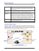
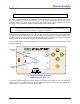
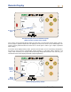
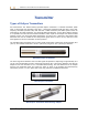
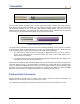
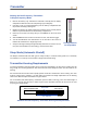
Table Of Contents
- Operator’s Manual
- Digital
- Control
- Incorporated
- DCI Headquarters 19625 62nd Ave. S., Suite B-103 Kent, Washington 98032 USA Tel 425 251 0559 / 800 288 3610 Fax 253 395 2800 E-mail DCI@digital-control.com www.digitrak.com
- Important Notice
- Safety Precautions and Warnings
- Safety Precautions and Warnings (Continued)
- _
- Introduction
- _
- Receiver
- Power On
- Toggle and Trigger Switches
- Speaker and Audible Tones
- Adjusting Screen Contrast
- Main Menu
- Locate Menu
- Set US Menu
- Low Fre/High Fre Menu
- Configure Menu
- Changing the Telemetry Channel
- 1-Point Calibration
- 2-Point Calibration (In-ground Calibration)
- Changing the Grade Mode
- Changing the Depth Measurement Mode
- Cold Screen / Normal Screen
- Tele Option A/B
- Locator DL / No Locator DL (Enabling and Disabling DataLog Menus)
- Set Roll / Unset Roll (Enabling and Disabling Roll Offset Function)
- Remote Display
- _
- Transmitter
- _
- Battery Charger
- _
- Locating
- _
- The Target Steering® Function
- _
- Cable System
- Cable System Components
- Non-DCI Supplies Required for Operating the Cable System
- Connecting Power Supply to Power Source and Cable Transmitter
- Grounding the Cable Transmitter
- Cable Transmitter On/Off
- Calibrating the Cable Transmitter
- Enabling the Roll Offset Function on the Remote Display
- Locating Using the Cable System
- Viewing Transmitter Depth or Predicted Depth
- Viewing Status of Cable System Power Source
- Target Steering Function Using the Cable System
- Troubleshooting
- _
- Appendix
- Depth Increase in Inches (Centimeters) per 6-foot (1.8 meter) Rod
- Depth Increase in Inches (Centimeters) per 10-foot (3-meter) Rod
- Depth Increase in Inches (Centimeters) per 15-foot (4.6-meter) Rod
- Percent of Grade to Degree Conversions (0.1% Pitch Transmitters or Sensitive Pitch)
- Degree to Percent of Grade Conversions (0.1% Pitch Transmitters)
- Calculating Depth Based on Distance Between FLP and RLP
- LIMITED WARRANTY

Transmitter
Starting the Eclipse Dual-Frequency Transmitter
The Eclipse dual-frequency transmitter can be set to transmit in two different modes—dual-frequency
mode (transmitting at 1.5 kHz and 12 kHz) or single-frequency mode (transmitting at 12 kHz).
The frequency mode can only be changed at startup when the batteries are loaded. You cannot change
the frequency mode of the transmitter while drilling.
The frequency mode is established by the orientation of the transmitter at startup, when the batteries are
loaded into the battery compartment.
Starting the Dual-Frequency Transmitter
in Dual-Frequency Mode
Loading Batteries
for Dual Mode
1. Remove the battery cap, and hold the transmitter vertically with the battery
compartment up and the front end pointing down (see diagram).
2. Load two C-cells (or a SuperCell lithium battery) into the battery compart-
ment with the positive terminal entering first.
3. Replace the battery cap while rotating the transmitter in this vertical position
until the cap is flush with the end of the battery compartment.
4. Power up the receiver, and verify that the main menu option shows Low Fre
on the main menu screen.
5. Select Locate from the receiver’s main menu screen, and click the trigger.
6. You will see DH above the thermometer on the left side of the screen to
indicate the transmitter is in dual-high mode.
7. Verify that the signal strength is 530 to 540 by placing the receiver 10 ft
(3 m) from the transmitter (in the housing), and record the value.
8. Return to the main menu screen on the receiver, select Low Fre, and click
the trigger.
9. Select Locate from the main screen, and click the trigger.
10. You will see DL above the thermometer on the left side of the screen to indicate the transmitter is in
dual-low mode.
11. Verify that the signal strength is 480 to 490 when the receiver is 10 ft (3 m) from the transmitter (in the
housing), and record the value.
DigiTrak
®
Eclipse
®
Operator’s Manual 39