
User's Manual
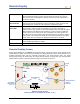
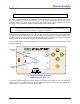
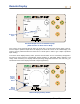
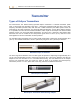
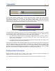
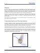
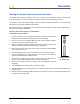
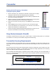
Table Of Contents
- Operator’s Manual
- Digital
- Control
- Incorporated
- DCI Headquarters 19625 62nd Ave. S., Suite B-103 Kent, Washington 98032 USA Tel 425 251 0559 / 800 288 3610 Fax 253 395 2800 E-mail DCI@digital-control.com www.digitrak.com
- Important Notice
- Safety Precautions and Warnings
- Safety Precautions and Warnings (Continued)
- _
- Introduction
- _
- Receiver
- Power On
- Toggle and Trigger Switches
- Speaker and Audible Tones
- Adjusting Screen Contrast
- Main Menu
- Locate Menu
- Set US Menu
- Low Fre/High Fre Menu
- Configure Menu
- Changing the Telemetry Channel
- 1-Point Calibration
- 2-Point Calibration (In-ground Calibration)
- Changing the Grade Mode
- Changing the Depth Measurement Mode
- Cold Screen / Normal Screen
- Tele Option A/B
- Locator DL / No Locator DL (Enabling and Disabling DataLog Menus)
- Set Roll / Unset Roll (Enabling and Disabling Roll Offset Function)
- Remote Display
- _
- Transmitter
- _
- Battery Charger
- _
- Locating
- _
- The Target Steering® Function
- _
- Cable System
- Cable System Components
- Non-DCI Supplies Required for Operating the Cable System
- Connecting Power Supply to Power Source and Cable Transmitter
- Grounding the Cable Transmitter
- Cable Transmitter On/Off
- Calibrating the Cable Transmitter
- Enabling the Roll Offset Function on the Remote Display
- Locating Using the Cable System
- Viewing Transmitter Depth or Predicted Depth
- Viewing Status of Cable System Power Source
- Target Steering Function Using the Cable System
- Troubleshooting
- _
- Appendix
- Depth Increase in Inches (Centimeters) per 6-foot (1.8 meter) Rod
- Depth Increase in Inches (Centimeters) per 10-foot (3-meter) Rod
- Depth Increase in Inches (Centimeters) per 15-foot (4.6-meter) Rod
- Percent of Grade to Degree Conversions (0.1% Pitch Transmitters or Sensitive Pitch)
- Degree to Percent of Grade Conversions (0.1% Pitch Transmitters)
- Calculating Depth Based on Distance Between FLP and RLP
- LIMITED WARRANTY

DIGITAL CONTROL INCORPORATED
Transmitter
Types of Eclipse Transmitters
DCI manufactures four different battery-operated Eclipse transmitters—a standard transmitter (black
tube), a short-range mini transmitter (gray tube), a long-range transmitter (light-gray tube), and a dual-
frequency transmitter (lavender tube). We also offer a cable transmitter (see Cable System section for
information on the cable transmitter). For especially difficult locating jobs, such as when walkover locating
is not possible, DCI offers the SST wireline transmitter, which is part of the Eclipse SST advanced HDD
guidance system. For deep auger-boring applications, we offer a 60-in. (1524-mm) auger-boring cable
transmitter that can be tracked for line and precision grade down to 200 ft (61 m). Call DCI or visit
www.digitrak.com for more information on these products.
The standard Eclipse transmitter emits a 12-kHz signal and provides a depth range of approximately 50 ft
(15.2 m). The standard transmitter is 15.00 in. (381.0 mm) long and 1.25 in. (31.8 mm) in diameter.
Standard Eclipse Transmitter
The short-range mini transmitter emits a 12-kHz signal and provides a depth range of approximately 15 ft
(4.6 m). The mini transmitter is 8.00 in. (203.2 mm) long and 1.00 in. (25.4 mm) in diameter. DCI offers an
adapter for the mini transmitter to fit in a standard-sized housing. The outer dimensions of the adapter
with the mini transmitter inside are exactly the same as those of the standard and dual-frequency
transmitters (15.00 in. x 1.25 in. [381.0 mm x 31.8 mm]). Call DCI for additional information.
Mini Eclipse Transmitter
Mini Eclipse Transmitter with Housing Adapter
DigiTrak
®
Eclipse
®
Operator’s Manual 35