
User's Manual
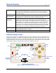
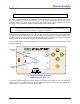
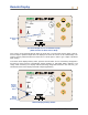
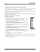
Table Of Contents
- Operator’s Manual
- Digital
- Control
- Incorporated
- DCI Headquarters 19625 62nd Ave. S., Suite B-103 Kent, Washington 98032 USA Tel 425 251 0559 / 800 288 3610 Fax 253 395 2800 E-mail DCI@digital-control.com www.digitrak.com
- Important Notice
- Safety Precautions and Warnings
- Safety Precautions and Warnings (Continued)
- _
- Introduction
- _
- Receiver
- Power On
- Toggle and Trigger Switches
- Speaker and Audible Tones
- Adjusting Screen Contrast
- Main Menu
- Locate Menu
- Set US Menu
- Low Fre/High Fre Menu
- Configure Menu
- Changing the Telemetry Channel
- 1-Point Calibration
- 2-Point Calibration (In-ground Calibration)
- Changing the Grade Mode
- Changing the Depth Measurement Mode
- Cold Screen / Normal Screen
- Tele Option A/B
- Locator DL / No Locator DL (Enabling and Disabling DataLog Menus)
- Set Roll / Unset Roll (Enabling and Disabling Roll Offset Function)
- Remote Display
- _
- Transmitter
- _
- Battery Charger
- _
- Locating
- _
- The Target Steering® Function
- _
- Cable System
- Cable System Components
- Non-DCI Supplies Required for Operating the Cable System
- Connecting Power Supply to Power Source and Cable Transmitter
- Grounding the Cable Transmitter
- Cable Transmitter On/Off
- Calibrating the Cable Transmitter
- Enabling the Roll Offset Function on the Remote Display
- Locating Using the Cable System
- Viewing Transmitter Depth or Predicted Depth
- Viewing Status of Cable System Power Source
- Target Steering Function Using the Cable System
- Troubleshooting
- _
- Appendix
- Depth Increase in Inches (Centimeters) per 6-foot (1.8 meter) Rod
- Depth Increase in Inches (Centimeters) per 10-foot (3-meter) Rod
- Depth Increase in Inches (Centimeters) per 15-foot (4.6-meter) Rod
- Percent of Grade to Degree Conversions (0.1% Pitch Transmitters or Sensitive Pitch)
- Degree to Percent of Grade Conversions (0.1% Pitch Transmitters)
- Calculating Depth Based on Distance Between FLP and RLP
- LIMITED WARRANTY

Remote Display
NOTE: The receiver must be in locate mode to send signals to the remote display.
The depth or predicted depth of the transmitter can also be viewed on the remote display. The receiver
must be positioned over either the locate line (LL) or one of the locate points (FLP or RLP) for this
function to work—see “Locate Points (FLP & RLP) and Locate Line (LL)” in the Locating section. Also,
this function is only available on Eclipse systems produced after February 2002.
NOTE: The capability to view the depth and predicted depth screens on the remote display is a
function that was added in February 2002. Older systems did not have this function. If you
have an older system and would like to upgrade, contact DCI.
Once the receiver is positioned over the LL, FLP, or RLP, the receiver operator holds in the trigger to take
the depth or predicted depth reading. The remote display will emit a single tone to notify the operator that
the depth information is being displayed. This depth/predicted depth information will remain on the remote
display’s screen for 10 seconds or as long as the receiver’s trigger is held in.
To view a depth reading on the remote display, the receiver must be above the transmitter or the LL while
the trigger is held in.
CH:B1
75
°
F
-1.5
%
Ultrasonic
Setting
Depth
Reading
Depth Screen on Remote Display
(when receiver is above LL)
To view the predicted depth on the remote display, the receiver must be above the FLP or RLP while the
trigger is held in. The predicted depth will only be valid if the receiver is over the FLP; data will appear if
the receiver is over the RLP, but the data will be invalid.
DigiTrak
®
Eclipse
®
Operator’s Manual 33