
User's Manual
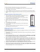
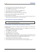
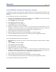
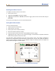
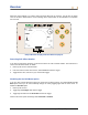
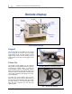
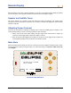
Table Of Contents
- Operator’s Manual
- Digital
- Control
- Incorporated
- DCI Headquarters 19625 62nd Ave. S., Suite B-103 Kent, Washington 98032 USA Tel 425 251 0559 / 800 288 3610 Fax 253 395 2800 E-mail DCI@digital-control.com www.digitrak.com
- Important Notice
- Safety Precautions and Warnings
- Safety Precautions and Warnings (Continued)
- _
- Introduction
- _
- Receiver
- Power On
- Toggle and Trigger Switches
- Speaker and Audible Tones
- Adjusting Screen Contrast
- Main Menu
- Locate Menu
- Set US Menu
- Low Fre/High Fre Menu
- Configure Menu
- Changing the Telemetry Channel
- 1-Point Calibration
- 2-Point Calibration (In-ground Calibration)
- Changing the Grade Mode
- Changing the Depth Measurement Mode
- Cold Screen / Normal Screen
- Tele Option A/B
- Locator DL / No Locator DL (Enabling and Disabling DataLog Menus)
- Set Roll / Unset Roll (Enabling and Disabling Roll Offset Function)
- Remote Display
- _
- Transmitter
- _
- Battery Charger
- _
- Locating
- _
- The Target Steering® Function
- _
- Cable System
- Cable System Components
- Non-DCI Supplies Required for Operating the Cable System
- Connecting Power Supply to Power Source and Cable Transmitter
- Grounding the Cable Transmitter
- Cable Transmitter On/Off
- Calibrating the Cable Transmitter
- Enabling the Roll Offset Function on the Remote Display
- Locating Using the Cable System
- Viewing Transmitter Depth or Predicted Depth
- Viewing Status of Cable System Power Source
- Target Steering Function Using the Cable System
- Troubleshooting
- _
- Appendix
- Depth Increase in Inches (Centimeters) per 6-foot (1.8 meter) Rod
- Depth Increase in Inches (Centimeters) per 10-foot (3-meter) Rod
- Depth Increase in Inches (Centimeters) per 15-foot (4.6-meter) Rod
- Percent of Grade to Degree Conversions (0.1% Pitch Transmitters or Sensitive Pitch)
- Degree to Percent of Grade Conversions (0.1% Pitch Transmitters)
- Calculating Depth Based on Distance Between FLP and RLP
- LIMITED WARRANTY

DIGITAL CONTROL INCORPORATED
Remote Display
Keypad
Display
Screen
Toggle
Arrows
Inf
r
ared
Port
Mounting
Bracket
Execute
Button
Eclipse Remote Display
Keypad
On the right side of the display is the keypad
used to operate the remote. The four toggle
arrow buttons serve the same purpose as the
toggle on the receiver, and the execute (curved
arrow) button is the same as the trigger on the
receiver.
Power On
The Eclipse remote display can be powered
using either a rechargeable DCI battery pack or
an Eclipse DC adapter (ELP). To power the
remote display using a rechargeable battery
pack, place the battery pack into the back of the
remote so that the two exposed terminals make
contact with the bottom two springs in the bat-
tery compartment
To power the remote display using an ELP,
place the ELP into the back of the remote so
that the three metal terminals make contact with
the three springs in the remote display. Then
plug the DC connector into the drill rig’s
cigarette lighter.
Installing Battery in Remote Display
ELP – Eclipse DC Adapter
Metal
Terminals
DC
Connector
Springs
Exposed
Terminals
Battery
Pack
DigiTrak
®
Eclipse
®
Operator’s Manual 29