
User's Manual
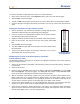
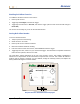
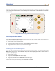
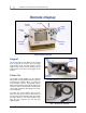
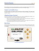
Table Of Contents
- Operator’s Manual
- Digital
- Control
- Incorporated
- DCI Headquarters 19625 62nd Ave. S., Suite B-103 Kent, Washington 98032 USA Tel 425 251 0559 / 800 288 3610 Fax 253 395 2800 E-mail DCI@digital-control.com www.digitrak.com
- Important Notice
- Safety Precautions and Warnings
- Safety Precautions and Warnings (Continued)
- _
- Introduction
- _
- Receiver
- Power On
- Toggle and Trigger Switches
- Speaker and Audible Tones
- Adjusting Screen Contrast
- Main Menu
- Locate Menu
- Set US Menu
- Low Fre/High Fre Menu
- Configure Menu
- Changing the Telemetry Channel
- 1-Point Calibration
- 2-Point Calibration (In-ground Calibration)
- Changing the Grade Mode
- Changing the Depth Measurement Mode
- Cold Screen / Normal Screen
- Tele Option A/B
- Locator DL / No Locator DL (Enabling and Disabling DataLog Menus)
- Set Roll / Unset Roll (Enabling and Disabling Roll Offset Function)
- Remote Display
- _
- Transmitter
- _
- Battery Charger
- _
- Locating
- _
- The Target Steering® Function
- _
- Cable System
- Cable System Components
- Non-DCI Supplies Required for Operating the Cable System
- Connecting Power Supply to Power Source and Cable Transmitter
- Grounding the Cable Transmitter
- Cable Transmitter On/Off
- Calibrating the Cable Transmitter
- Enabling the Roll Offset Function on the Remote Display
- Locating Using the Cable System
- Viewing Transmitter Depth or Predicted Depth
- Viewing Status of Cable System Power Source
- Target Steering Function Using the Cable System
- Troubleshooting
- _
- Appendix
- Depth Increase in Inches (Centimeters) per 6-foot (1.8 meter) Rod
- Depth Increase in Inches (Centimeters) per 10-foot (3-meter) Rod
- Depth Increase in Inches (Centimeters) per 15-foot (4.6-meter) Rod
- Percent of Grade to Degree Conversions (0.1% Pitch Transmitters or Sensitive Pitch)
- Degree to Percent of Grade Conversions (0.1% Pitch Transmitters)
- Calculating Depth Based on Distance Between FLP and RLP
- LIMITED WARRANTY

Receiver
Enabling Roll Offset Function
To enable the roll offset function on the receiver:
1. Power up the receiver.
2. Toggle right to Configure, and click the trigger.
3. Toggle right several times to Set Roll, and click the trigger (note that this menu item will change to
Unset Roll).
The receiver is now ready for you to use the roll offset function.
Setting Roll Offset Number
To set the roll offset number:
1. Torque-up the tool to the housing.
2. Orient the tool to 12 o’clock.
3. Power up the receiver and the transmitter.
4. Place the transmitter inside the housing.
5. From the receiver’s main menu screen, select Locate and click the trigger.
6. Toggle right one time, select Y for yes, and click the trigger. The transmitter’s roll position should now
match the tool’s position, which is 12 o’clock.
The “Roll Offset” number will appear at the top of the receiver’s screen. This number is displayed to
indicate that a compensation for the transmitter’s roll position has occurred. This number will remain in
memory until you change it; therefore, you can calibrate, change the telemetry channel, and replace the
battery without affecting this roll offset number.
DL
7.5
%
CH:B1
411
75
°
F
R
oll Offset
:315
°
Eclipse Receiver with Roll Offset Displayed
DigiTrak
®
Eclipse
®
Operator’s Manual 27