
User's Manual
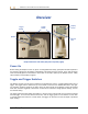
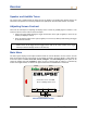
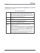
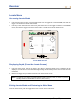
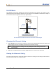
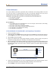
Table Of Contents
- Operator’s Manual
- Digital
- Control
- Incorporated
- DCI Headquarters 19625 62nd Ave. S., Suite B-103 Kent, Washington 98032 USA Tel 425 251 0559 / 800 288 3610 Fax 253 395 2800 E-mail DCI@digital-control.com www.digitrak.com
- Important Notice
- Safety Precautions and Warnings
- Safety Precautions and Warnings (Continued)
- _
- Introduction
- _
- Receiver
- Power On
- Toggle and Trigger Switches
- Speaker and Audible Tones
- Adjusting Screen Contrast
- Main Menu
- Locate Menu
- Set US Menu
- Low Fre/High Fre Menu
- Configure Menu
- Changing the Telemetry Channel
- 1-Point Calibration
- 2-Point Calibration (In-ground Calibration)
- Changing the Grade Mode
- Changing the Depth Measurement Mode
- Cold Screen / Normal Screen
- Tele Option A/B
- Locator DL / No Locator DL (Enabling and Disabling DataLog Menus)
- Set Roll / Unset Roll (Enabling and Disabling Roll Offset Function)
- Remote Display
- _
- Transmitter
- _
- Battery Charger
- _
- Locating
- _
- The Target Steering® Function
- _
- Cable System
- Cable System Components
- Non-DCI Supplies Required for Operating the Cable System
- Connecting Power Supply to Power Source and Cable Transmitter
- Grounding the Cable Transmitter
- Cable Transmitter On/Off
- Calibrating the Cable Transmitter
- Enabling the Roll Offset Function on the Remote Display
- Locating Using the Cable System
- Viewing Transmitter Depth or Predicted Depth
- Viewing Status of Cable System Power Source
- Target Steering Function Using the Cable System
- Troubleshooting
- _
- Appendix
- Depth Increase in Inches (Centimeters) per 6-foot (1.8 meter) Rod
- Depth Increase in Inches (Centimeters) per 10-foot (3-meter) Rod
- Depth Increase in Inches (Centimeters) per 15-foot (4.6-meter) Rod
- Percent of Grade to Degree Conversions (0.1% Pitch Transmitters or Sensitive Pitch)
- Degree to Percent of Grade Conversions (0.1% Pitch Transmitters)
- Calculating Depth Based on Distance Between FLP and RLP
- LIMITED WARRANTY

Receiver
Changing the Telemetry Channel
Telemetry is the wireless communication system used between the receiver and the remote display. The
receiver must be set to the same telemetry channel as the remote display at the drill. There are five
channel settings, including a setting of zero. There are actually only two frequencies—channels 1 and 3
operate at the same frequency, and channels 2 and 4 operate at the same frequency. The zero setting
will not send a signal, and it will also conserve the battery life in the receiver.
To change the telemetry channel:
1. Select Configure from the main menu screen, and click the trigger.
2. Select Tele Ch., and click the trigger. The current channel setting will be displayed.
3. Push the toggle up to advance the channel setting or pull the toggle down to decrease the channel
setting.
NOTE: The receiver must be set to the same channel as the remote display.
4. Once the desired channel is displayed, click the trigger.
5. To exit and return to the main menu, push the toggle down one time.
In addition to the telemetry channel settings, you may need to use the Tele Option A/B function. This
function is part of DCI’s most advanced telemetry system called TeleLock™ Technology (TLT). TLT
extends the telemetry range for longer bores and when the line of sight between the receiver and remote
display is compromised.
You must use the Tele Option A/B function
on the receiver to display Tele Option B (which means it is set
to Tele Option A) when operating a newer TLT receiver (serial number equal to or greater than EDRR
2690) and an older remote display (serial number less than EDD 2644). If you are operating an older
receiver (serial number less than EDRR 2690) with a newer remote display (serial number equal to or
greater than EDD 2644), then you must use the Tele Option A/B function
on the remote display to show
Tele Option B (see “Tele Option A/B” later in this section).
When using a newer receiver with TLT and an older remote display without TLT, you must change the
Tele Option A/B setting on the receiver to show Tele Option B:
1. Select Configure from the main menu screen, and click the trigger.
2. Toggle to the right several times to select Tele Option A, and click the trigger. Tele Option B will
now display, and this newer TLT receiver will now communicate with the older remote display.
When using an older receiver without TLT and a newer remote display with TLT, you must change the
Tele Option A/B setting on the remote display to show Tele Option B:
1. Select Configure from the main menu screen, and press the execute button.
2. Press the right arrow several times to select Tele Option A, and press the execute button. Tele
Option B will now display, and this newer TLT remote display will now communicate with the older
receiver.
You can upgrade your Eclipse receiver and remote display units to have the TLT or enhanced telemetry
function. If you are interested in doing so, please call DCI (425-251-0559 or 800-288-3610) to discuss.
For additional telemetry range, contact DCI to discuss alternate antenna options for your remote display.
18 DigiTrak
®
Eclipse
®
Operator’s Manual