
User's Manual
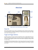
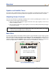
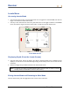
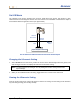
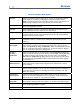
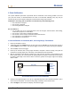
Table Of Contents
- Operator’s Manual
- Digital
- Control
- Incorporated
- DCI Headquarters 19625 62nd Ave. S., Suite B-103 Kent, Washington 98032 USA Tel 425 251 0559 / 800 288 3610 Fax 253 395 2800 E-mail DCI@digital-control.com www.digitrak.com
- Important Notice
- Safety Precautions and Warnings
- Safety Precautions and Warnings (Continued)
- _
- Introduction
- _
- Receiver
- Power On
- Toggle and Trigger Switches
- Speaker and Audible Tones
- Adjusting Screen Contrast
- Main Menu
- Locate Menu
- Set US Menu
- Low Fre/High Fre Menu
- Configure Menu
- Changing the Telemetry Channel
- 1-Point Calibration
- 2-Point Calibration (In-ground Calibration)
- Changing the Grade Mode
- Changing the Depth Measurement Mode
- Cold Screen / Normal Screen
- Tele Option A/B
- Locator DL / No Locator DL (Enabling and Disabling DataLog Menus)
- Set Roll / Unset Roll (Enabling and Disabling Roll Offset Function)
- Remote Display
- _
- Transmitter
- _
- Battery Charger
- _
- Locating
- _
- The Target Steering® Function
- _
- Cable System
- Cable System Components
- Non-DCI Supplies Required for Operating the Cable System
- Connecting Power Supply to Power Source and Cable Transmitter
- Grounding the Cable Transmitter
- Cable Transmitter On/Off
- Calibrating the Cable Transmitter
- Enabling the Roll Offset Function on the Remote Display
- Locating Using the Cable System
- Viewing Transmitter Depth or Predicted Depth
- Viewing Status of Cable System Power Source
- Target Steering Function Using the Cable System
- Troubleshooting
- _
- Appendix
- Depth Increase in Inches (Centimeters) per 6-foot (1.8 meter) Rod
- Depth Increase in Inches (Centimeters) per 10-foot (3-meter) Rod
- Depth Increase in Inches (Centimeters) per 15-foot (4.6-meter) Rod
- Percent of Grade to Degree Conversions (0.1% Pitch Transmitters or Sensitive Pitch)
- Degree to Percent of Grade Conversions (0.1% Pitch Transmitters)
- Calculating Depth Based on Distance Between FLP and RLP
- LIMITED WARRANTY

Receiver
Receiver Configure Menu Options
Tele Ch.
Changes the telemetry channel setting for the receiver to communicate with the
remote display at the drill (see “Changing the Telemetry Channel” section).
NOTE: The receiver must be set to the same channel as the remote display. The
channel setting is displayed on the lower left side of the locate screen.
1 Pt. Cal.
Initiates standard calibration procedure used with the transmitter above ground
(see “1-Point Calibration” section).
2 Pt. Cal.
Initiates calibration procedure used when the transmitter is below ground (see
“2-Point Calibration” section). Should be used with caution.
Target Depth
Allows you to program the transmitter’s depth at a prescribed distance ahead of
its current location. Used for Target Steering function (see The Target Steering
Function section later in this manual).
° Grade /
% Grade
Changes how the transmitter’s pitch information is displayed (see “Changing the
Grade Mode” section). The pitch can be displayed in percent slope (%) or in
degrees (°).
Use Metric /
Use English
Changes the depth measurement mode (see “Changing the Depth Measurement
Mode” section). The depth can be displayed in metric units or in three forms of
English units (IN Only, FT Only, or FT/IN Units). When measuring depth in metric
units, the transmitter temperature is displayed in °C; when measuring in English
units, the transmitter temperature is displayed in °F.
IN Only /
FT Only /
FT/IN Units
Changes the English units for the depth setting. Selecting IN Only will display the
depth in inches and change the menu option to show FT Only. Selecting FT Only
will display the depth in feet and will change the menu option to show FT/IN
Units. Selecting FT/IN Units will display depth in feet and inches and will change
the menu option to show IN Only. All these depth measurement options display
the temperature in °F.
Cold Screen /
Normal Screen
Changes from one contrast mode to the other—the screen can have a black
(cold) background or a light (normal) background (see “Cold Screen / Normal
Screen” section).
Tele Option A/B
Allows communication from a receiver to a remote display when they have
different telemetry systems, such as when one unit has TeleLock™ Technology or
TLT and the other does not (see “Changing the Telemetry Channel” and “Tele
Option A/B” sections).
Locator DL /
No Locator DL
Enables the DataLog Mapping System menu options so that you can access
DataLog functions from the Eclipse receiver’s main menu screen and store data
when locating (see “Locator DL / No Locator DL” section).
Set Roll /
Unset Roll
Enables the roll offset function, which allows the transmitter’s roll position to be
compensated to match the tool’s roll position (see “Set Roll / Unset Roll” section).
Code
This menu option is provided for DCI to use for calibration during manufacturing
and for diagnosing problems for repairs.
Exit
Returns display to the main menu screen.
DigiTrak
®
Eclipse
®
Operator’s Manual 17