
User's Manual
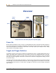
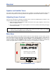
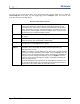
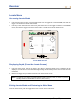
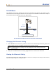
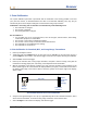
Table Of Contents
- Operator’s Manual
- Digital
- Control
- Incorporated
- DCI Headquarters 19625 62nd Ave. S., Suite B-103 Kent, Washington 98032 USA Tel 425 251 0559 / 800 288 3610 Fax 253 395 2800 E-mail DCI@digital-control.com www.digitrak.com
- Important Notice
- Safety Precautions and Warnings
- Safety Precautions and Warnings (Continued)
- _
- Introduction
- _
- Receiver
- Power On
- Toggle and Trigger Switches
- Speaker and Audible Tones
- Adjusting Screen Contrast
- Main Menu
- Locate Menu
- Set US Menu
- Low Fre/High Fre Menu
- Configure Menu
- Changing the Telemetry Channel
- 1-Point Calibration
- 2-Point Calibration (In-ground Calibration)
- Changing the Grade Mode
- Changing the Depth Measurement Mode
- Cold Screen / Normal Screen
- Tele Option A/B
- Locator DL / No Locator DL (Enabling and Disabling DataLog Menus)
- Set Roll / Unset Roll (Enabling and Disabling Roll Offset Function)
- Remote Display
- _
- Transmitter
- _
- Battery Charger
- _
- Locating
- _
- The Target Steering® Function
- _
- Cable System
- Cable System Components
- Non-DCI Supplies Required for Operating the Cable System
- Connecting Power Supply to Power Source and Cable Transmitter
- Grounding the Cable Transmitter
- Cable Transmitter On/Off
- Calibrating the Cable Transmitter
- Enabling the Roll Offset Function on the Remote Display
- Locating Using the Cable System
- Viewing Transmitter Depth or Predicted Depth
- Viewing Status of Cable System Power Source
- Target Steering Function Using the Cable System
- Troubleshooting
- _
- Appendix
- Depth Increase in Inches (Centimeters) per 6-foot (1.8 meter) Rod
- Depth Increase in Inches (Centimeters) per 10-foot (3-meter) Rod
- Depth Increase in Inches (Centimeters) per 15-foot (4.6-meter) Rod
- Percent of Grade to Degree Conversions (0.1% Pitch Transmitters or Sensitive Pitch)
- Degree to Percent of Grade Conversions (0.1% Pitch Transmitters)
- Calculating Depth Based on Distance Between FLP and RLP
- LIMITED WARRANTY

DIGITAL CONTROL INCORPORATED
Receiver
Display
Screen
Toggle
Switch
Trigge
r
Switch
Speake
r
Infrared
Port
Eclipse Receiver Side View (left) and Top View (right)
Power On
Before turning the Eclipse receiver on, place a rechargeable DCI battery pack (with terminals exposed to
the receiver’s springs) into the battery compartment at the back end of the receiver. Then, click the trigger
under the handle (push it in and release it in less than ½ second) to power up the Eclipse receiver. It may
take a moment for the display to appear.
Toggle and Trigger Switches
The Eclipse receiver has two types of switches for operating the system—a toggle (thumb switch) and a
trigger. The toggle switch is located on top of the handle. It moves in four different directions—left, right,
up, and down. Push the toggle left or right to move the menu arrows on the display to select the desired
menu item. Push the toggle up or down once a menu item is selected to change specific settings, such as
the channel setting.
The trigger switch is located under the handle. It is used to access a menu item once it has been selected
with the toggle. To access the selected menu item, click the trigger (push it in and release it in less than
½ second). When the receiver is in locate mode, the trigger can be held in to view the depth or predicted
depth reading.
DigiTrak
®
Eclipse
®
Operator’s Manual 11