
User's Manual
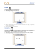
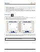
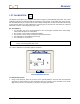
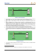
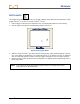
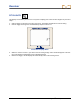
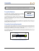
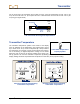
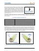
Table Of Contents
- Safety Precautions and Warnings
- Dear Customer:
- Introduction
- Receiver
- Transmitter
- Remote Display
- Battery Charger
- Locating Instructions
- Appendix A: System Specifications and Maintenance Requirements
- Appendix B: Projected Depth Versus Actual Depth and the Fore/Aft Offset
- Appendix C: Calculating Depth Based on Distance Between FLP and RLP
- LIMITED WARRANTY

Transmitter
DigiTrak
®
LT2™ Operator’s Manual 29
For the short-range LS2 transmitter (8.00 in./203 mm long), each slot should begin at least 1.25 in. (32
mm) and not more than 2 in. (51 mm)from the front of the transmitter and must be at least 3.75 in. (95
mm) long (see figure below).
Front
End
Back
End
3.75 in.
95 mm
1.25 in.
32 mm
Slot Position
LS2 Transmitter Housing Slot Requirements
Transmitter Temperature
The transmitter temperature symbol at the bottom of the display
gives an indication of the temperature, with progress bars and an
up or down arrow. An up arrow accompanied by a beep indicates
the temperature is increasing; a down arrow indicates the tempera-
ture is decreasing. A digital temperature reading can be viewed
below the clock in place of the pitch by holding in the trigger. The
drill rig operator can view the transmitter temperature by holding in the function button on the remote
display. Drilling should be suspended when temperatures reach 95°F (35°C) to permit cooling.
Receiver Display Screen Showing Remote Display Screen Showing
Transmitter Temperature Transmitter Temperature
Transmitter Temperature
Display Symbol